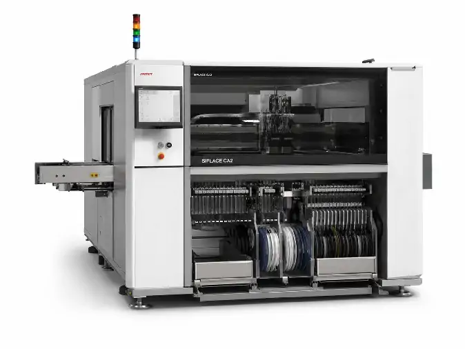
ASMPT SIPLACE CA2 Pick and Place Machine
Review ASMPT SIPLACE CA2 specifications for hybrid SMD and direct wafer die placement, including speed, accuracy, component range, wafe...
View Machine Details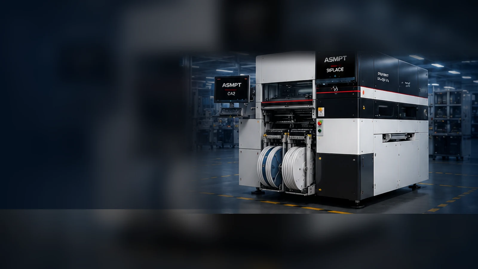
SIPLACE CA2 combines feeder-supplied SMD placement with direct wafer-fed die handling. This page keeps the published platform specifications visible while helping you translate a real product requirement into the placement heads, wafer hardware, transport and software that should be checked on a candidate used machine.
Reference image only. Current availability and the installed configuration of any offered machine must be confirmed separately.
Review the CA2 listings currently published on the website, then open the individual record to check the machine-specific information available for that unit.
Review ASMPT SIPLACE CA2 specifications for hybrid SMD and direct wafer die placement, including speed, accuracy, component range, wafe...
View Machine DetailsPublished records identify individual equipment listings. Availability, installed options, condition, included accessories and delivery scope must still be confirmed for the specific machine.
CA2 is worth reviewing when the same product needs conventional SMD placement and dies supplied directly from a sawn wafer. That combination is the platform's defining role, but it is only the first part of the buying decision.
A candidate machine still needs the correct placement head, wafer system, substrate transport and software environment. The purpose of this page is to connect the published CA2 capability with the actual machine build you may be offered.
The key question is not whether CA2 is technically impressive, but whether its mixed material flow solves the product and production problem you actually have.
Reel-fed and supported feeder-supplied components enter the SMT placement side of the process.
Bare dies are picked directly from a sawn wafer for die-attach or flip-chip placement.
These figures remain useful for early screening. They describe the published CA2 platform, while the installed options, condition and usable output of a specific used machine still need to be confirmed.
Buying context: Published values help position the platform. A candidate machine still needs the correct head, wafer hardware, transport, software and supporting records for the intended process.
You should not have to decode the entire machine configuration on your own. Start with the product, wafer input, substrate and factory environment; those needs can then be compared with the documented build of the candidate machine and separated into likely fit, configuration gaps and open points.
The component and die mix, placement mode, target accuracy, throughput direction and any low-force, no-contact or dipping requirement.
The documented placement-head build, accuracy class, vision options, supported range, process modules and available calibration or acceptance records.
A missing head, camera or process option may mean additional hardware, tooling or qualification work before the product can be introduced.
The wafer and frame format, carrier film, die range, mapping method, traceability level and required wafer capacity.
The installed wafer changer, tables or chucks, ejector, buffer, mapping support and documented compatibility with the target wafer format.
A mismatch can lead to additional wafer hardware, custom tooling, software setup or process development rather than a simple machine installation.
The substrate or panel dimensions, lanes, carrier concept, product support, warpage conditions and line-flow arrangement.
The installed single- or dual-track system, usable width, flow direction, support hardware and relevant carrier or inspection options.
The placement process may fit while the transport does not, creating additional conveyor, carrier, support or line-integration work.
The recipe, die-level traceability, production data, MES connection, communication protocol and documentation expected by the factory.
The documented software version, available licenses and backups, WORKS modules, protocols, interfaces and supporting machine records.
A machine may run independently but still require licensing, data preparation, interface work or additional documentation before line integration.
The first conversation does not need to begin with a complete CA2 configuration sheet. A short description of the product and production flow gives us a practical starting point for reviewing the available candidate information.
Share the material streams, substrate, target accuracy, output direction, wafer presentation and factory requirements that matter to the project.
A concise application summary is enough to begin. We can identify which machine details are still needed.
We organize the available machine identity, heads, wafer system, transport, software, documentation and condition evidence around your process requirement.
Confirmed items, likely gaps and undocumented points are separated instead of being hidden inside a generic model quotation.
The quotation can identify the candidate machine, documented configuration, included tooling and accessories, software or files, and agreed packing and delivery scope.
Open points, seller-dependent confirmation and possible additional engineering are listed separately.
The review keeps confirmed information, configuration gaps and unresolved items visible before a machine scope is priced.
Not sure which CA2 configuration your process needs? Start with the product, wafer input and substrate format. We will organize the machine-level questions from there.
Start a CA2 Configuration ReviewASMPT describes CA2 as a combination of an SMT placement machine and a die bonder. It can place feeder-supplied SMDs and dies taken directly from sawn wafers in one work step, subject to the installed machine configuration.
No. Published values describe the platform and its available accuracy classes. The actual result depends on the installed heads, process mode, component mix, transport, software, maintenance condition and agreed acceptance method.
No. A short explanation of the product, material inputs, substrate, target accuracy and production environment is enough for the first review. The missing machine-level questions can then be organized around that application.
The useful next step is to separate manageable conversion work from fundamental process mismatches. Missing tooling, software or a specific option may be addressable, while a different material flow or transport concept may point to another equipment direction.
Tell us what the product and process require. We will organize the available candidate information around that requirement and clarify the likely fit, configuration gaps and quotation scope.