Pick, Orient and Present the Die
The machine retrieves a singulated die from wafer tape, tray, waffle pack or another carrier, controls its orientation and presents the bumped surface toward the target.
A flip chip bonder picks and orients a bumped die face-down, aligns its bumps or copper pillars with matching pads, and places or bonds the die to a substrate, wafer or another chip. Explore equipment for thermocompression bonding, mass-reflow placement, chip-to-substrate, chip-to-wafer, silicon photonics and other high-density interconnect applications.
Unlike conventional face-up die attach, flip chip assembly places the active side of the die toward the receiving pads. The bonder must control orientation, two-sided alignment, coplanarity, bond force and the selected joining conditions without damaging the die, bumps or substrate.
The exact sequence changes with mass reflow, thermocompression, thermosonic, adhesive or direct bonding, but the following four machine functions remain central to equipment selection.
The machine retrieves a singulated die from wafer tape, tray, waffle pack or another carrier, controls its orientation and presents the bumped surface toward the target.
Up-looking and down-looking optics, pattern recognition and stage correction align die features with substrate, interposer, wafer or second-die targets.
The platform manages tip and tilt, placement height, force, temperature, atmosphere, dwell time and optional ultrasonic or curing functions according to the qualified process.
After joining or tack placement, the tool releases the device and may perform post-bond measurement, inspection, recipe logging and traceability before the next cycle.
Both processes create electrical connections from the semiconductor die to the package, but the connection geometry and required equipment are different. This page focuses specifically on direct face-down connection through bumps, pillars or prepared bonding surfaces.
Review available flip chip bonding machines, precision placement platforms and thermocompression bonding systems. Send the die, interconnect, target substrate, joining route and production requirement to compare actual machine configurations.
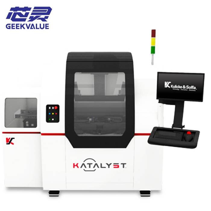
Evaluate the Kulicke & Soffa Katalyst flip chip mounter for micro LED mass transfer and advanced RF
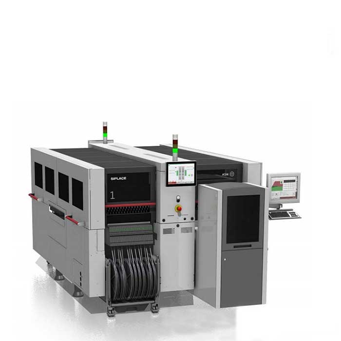
Evaluate semiconductor flip chip placement machines for advanced packaging. Compare mass reflow and TCB systems for fine...
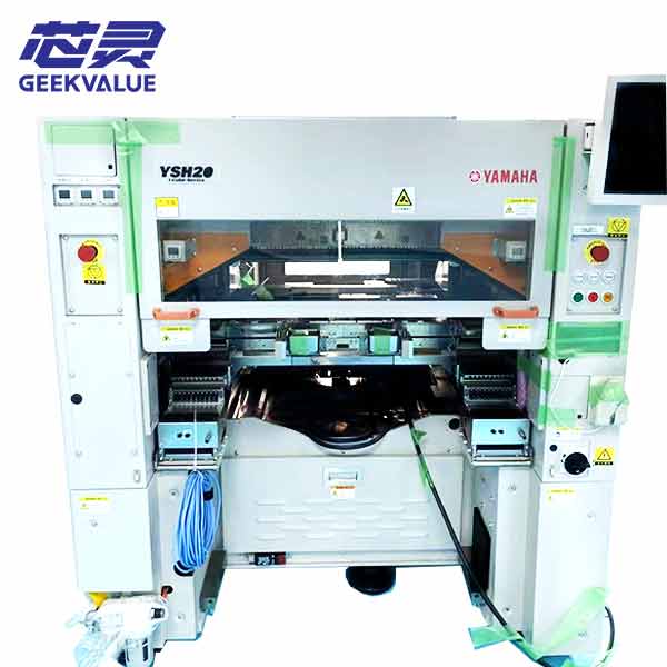
Evaluate the Yamaha YSH20 for high-volume LED, RF, and small die placement. Combines SMT-level speed with micron accurac...
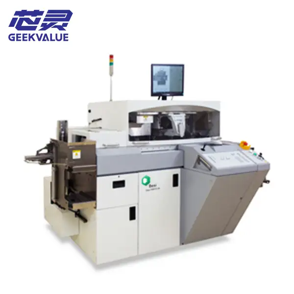
Evaluate the BESI Esec 2100 FC hS flip chip bonder for high-volume advanced packaging. Delivers 8μm accuracy at up to 16...
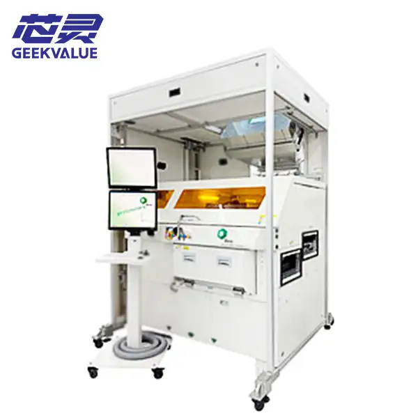
Evaluate the Besi Datacon 8800 CHAMEO ultra for sub-micron flip chip and thermocompression bonding. Ideal for silicon ph...
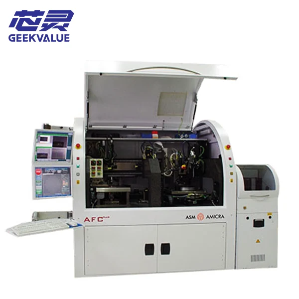
Evaluate the ASM AFC Plus flip chip bonder for high-density semiconductor packaging. Delivers sub-micron alignment and p...
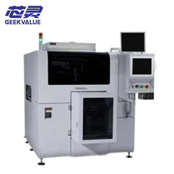
Evaluate the SHIBAURA TFC-9000 flip chip bonder for advanced optoelectronics and RF packaging. Delivers stable alignment...
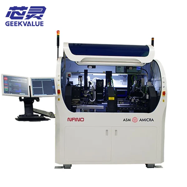
Evaluate the ASMPT AMICRA NANO ultra-precision flip chip bonder for sub-micron optoelectronic and RF packaging. Supports...
The best platform depends on whether the project is developing a new interconnect, transferring a stable process into pilot production or operating a repeatable high-volume line.
Do not select by advertised accuracy alone. Operator access, material presentation, recipe development, process data, cycle time, traceability and factory integration can be equally important.
Discuss Your Production StageManual or assisted systems prioritize optical access, flexible tooling, controlled experiments and the ability to evaluate different dies, targets, forces, temperatures and joining methods.
Semi-automatic or versatile platforms add programmable motion, process repeatability, measurement and data logging while retaining flexibility for engineering changes and limited production.
Production systems emphasize wafer, tray or carrier automation, short cycle time, stable recipe execution, inspection, host communication, traceability and predictable equipment utilization.
“Flip chip” describes the assembly orientation, not one universal bonding recipe. The interconnect metallurgy and required joint formation determine the bond head, thermal system, atmosphere, force control and handling options.
Confirm bond-force range, top and bottom heating, temperature uniformity, dwell time, active tip and tilt, atmosphere, cooling, die warpage and the method used to verify post-bond accuracy. TCB capability depends on the installed hardware, not only the platform name.
Review flux application, tack placement, stage heating, die stability, substrate support, reflow flow, cooling and post-placement handling. A mass-reflow placement platform and a dedicated TCB system are not automatically interchangeable.
Verify the ultrasonic module, heating method, dispensing or stamping, bond-line control, UV access, tool interface and compatible process monitoring. These options are configuration-specific.
Direct or hybrid bonding normally requires dedicated environmental control, surface preparation, particle management, parallelism, low-force contact and post-bond thermal processing. Do not assume a standard solder-bump bonder can perform this process.
A laboratory alignment bonder, a high-force process-development platform and a fully automatic thermocompression production system belong to different equipment classes. One generic price range would not describe them accurately.
A comparable quotation must identify the actual installed process package, handling modules, calibration condition, tooling and support scope—not only the model printed on the machine.
Send the preferred model or application, die and target format, interconnect process, accuracy, automation level, condition and destination.
Request Current Availability →Optics, bond head, force range, parallelism, heating, atmosphere and inspection options determine the processes the machine can actually support.
Wafer stages, ejectors, trays, flip tools, chucks, collets, substrate fixtures and automation modules can materially change quotation scope.
Licenses, recipe functions, camera calibration, force and thermal verification, post-bond measurement and demonstration evidence affect readiness.
Manufacturing year, operating history, replaced parts, documentation, packing, installation, training and after-sales scope affect delivered cost.
Headline values are useful only when the test condition and installed configuration are known. Compare these specification groups against the actual package and process instead of selecting from a single advertised number.
Confirm whether accuracy is measured before contact or after the full heat-and-force cycle, the sigma level used, the die size, field position, temperature and measurement method.
Review minimum and maximum force, control resolution, active tip and tilt, coplanarity, final gap measurement and the ability to protect fragile or warped components.
Compare maximum temperature, ramp rate, uniformity, pulse or stage heating, cooling, thermal expansion compensation and compatibility with the required process window.
Confirm minimum and maximum die size, thickness, wafer diameter, tape frame, tray or waffle-pack input, substrate dimensions, carrier type and automatic loading options.
Identify inert gas, vacuum, formic-acid or fluxless processing, particle control, clean-environment requirements and whether the enclosure matches the intended material system.
Evaluate cycle time using the real process, material changeover, recipe management, post-bond inspection, data collection, host communication and maintenance access.
Used equipment can shorten lead time and reduce capital cost, but a model name does not reveal its current accuracy, installed process modules or included tooling.
The review should connect machine identity and condition to the target package, interconnect and acceptance criteria.
Confirm the complete designation, manufacturing year, serial information, machine location, ownership history and current operating status.
Review cameras, illumination, pattern recognition, stage calibration, post-bond measurement method, repeatability results and parallelism verification.
Identify force range, tool interface, top and bottom heating, cooling, temperature controllers, tip and tilt hardware and process-specific modules.
List wafer stage, ejector, die input, trays, chucks, collets, flip tools, substrate fixtures, carriers and included change parts.
Confirm the atmosphere enclosure, gas controls, vacuum, flux or fluxless route, ultrasonic hardware, dispensing, stamping and UV capability where required.
Check the PC, software versions, licenses, manuals, maintenance records, refurbishment work, spare parts, test samples and available live or recorded demonstration.
These answers clarify equipment scope, process compatibility, specification comparison, used-machine inspection and the information needed for a useful quotation.
A flip chip bonder is semiconductor assembly equipment that picks and orients a bumped die face-down, aligns its bumps or pillars with matching pads, and places or bonds it to a substrate, wafer or another die under controlled force, temperature, atmosphere and parallelism.
A conventional die bonder usually places a die onto adhesive, solder or another attach material with the active side facing up. A flip chip bonder aligns a bumped active surface face-down for direct connection to matching pads. Some modular platforms support both, but the installed optics, bond head, heating and handling must be verified.
Depending on configuration, a platform may support mass-reflow placement, thermocompression bonding, thermosonic bonding, eutectic or solder joining, adhesive bonding, UV curing and selected direct or hybrid bonding processes.
Compare placement or post-bond accuracy together with the measurement method, sigma level, die size, temperature, field position and whether the value is measured before or after the complete bonding cycle.
Some platforms can support both C2S and C2W, but wafer stages, substrate handling, die input, optics, tooling, software and process modules differ. Compatibility must be confirmed from the actual installed configuration.
Price depends on equipment class, accuracy, force, heating, atmosphere, wafer and substrate handling, automation, software, tooling, year, condition and support scope. A useful quotation requires the target process and offered configuration.
Verify the complete model and suffix, serial number, year, alignment system, calibration, bond head, force, heating, parallelism, handling modules, atmosphere options, software, tooling, service history and available demonstration evidence.
Provide die, bump and substrate details, C2S or C2W format, joining process, post-bond accuracy, force and temperature window, atmosphere, automation level, preferred condition, destination and project schedule.
Send the die, bump or pillar, substrate or wafer format, required post-bond accuracy, joining method, force and temperature window, production stage, preferred machine condition and destination.