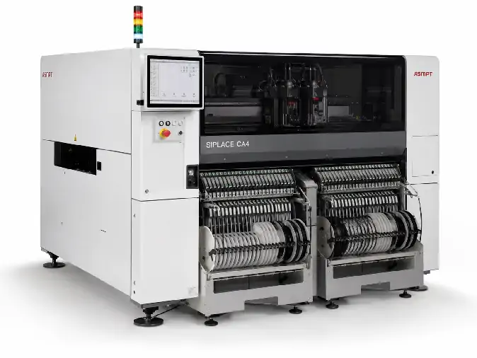
ASMPT SIPLACE CA4 Chip Assembly Machine
Review ASMPT SIPLACE CA4 specifications for SMD, direct die attach and flip-chip placement, including speed, accuracy, wafer handling a...
Просмотреть подробные сведения о машине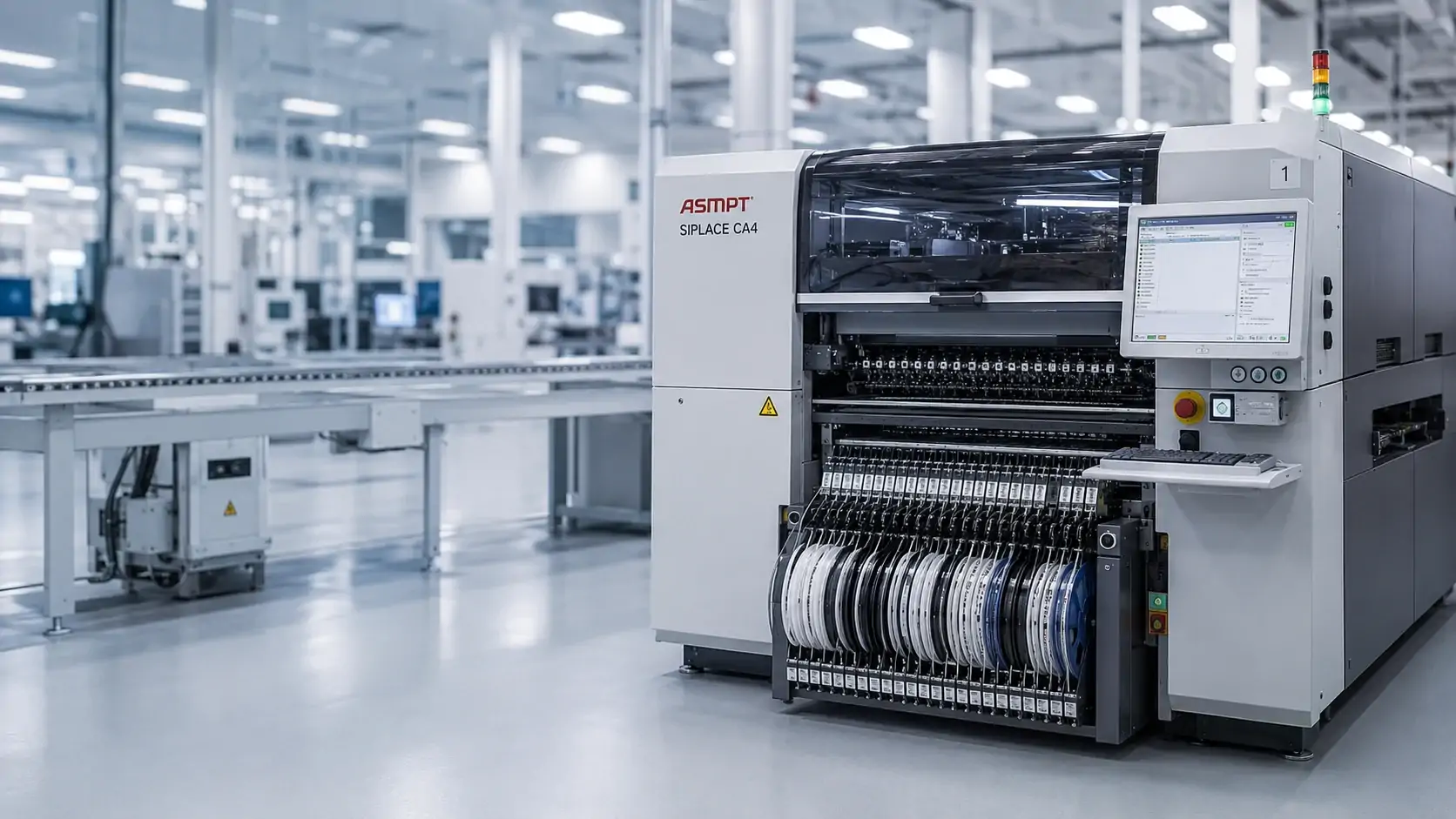
SIPLACE CA4 is more than a conventional SMT pick-and-place machine. It is a chip-assembly platform that can combine feeder-supplied SMDs with dies taken directly from wafers. Its four configurable material positions can support wafer systems, feeder changeover tables or a mixed setup, making the platform relevant to SiP, advanced packaging and other products that bring SMT and semiconductor assembly together. The actual value of a used CA4 still depends on the heads, wafer hardware, conveyor, software and tooling installed on that specific machine.
Изображение приведено только для справки. Наличие и конфигурация предлагаемого оборудования должны быть подтверждены отдельно.
Review the CA4 listings currently published on the website, then confirm whether each unit is configured for feeder-based SMT placement, direct wafer die handling, flip-chip work or a mixed SMD-and-die production flow.
Review ASMPT SIPLACE CA4 specifications for SMD, direct die attach and flip-chip placement, including speed, accuracy, wafer handling a...
Просмотреть подробные сведения о машинеPublished records identify individual equipment listings. Availability, four-position allocation, installed heads, wafer systems, transport, software, included accessories and delivery scope must still be confirmed for the specific machine.
SIPLACE CA4 combines feeder-based SMD placement with direct handling of semiconductor dies from compatible wafers. Depending on the installed modules, it can support conventional SMT placement, die attach, flip-chip placement or a mixed assembly flow.
Its four material positions can be allocated to SIPLACE Wafer Systems or feeder changeover tables, allowing SMT-heavy, wafer-heavy or mixed SiP production. For a used machine, the actual heads, wafer hardware, transport, software and tooling must still be confirmed.
Wafer System or feeder changeover table.
Adds a second wafer-fed or feeder-supplied source.
Expands die variety, feeder capacity or the SMT-to-wafer balance.
Completes the material mix required by the product flow.
The four-position allocation determines whether a specific CA4 is built mainly for SMT placement, direct wafer die placement or mixed semiconductor assembly. Illustrative only; confirm the actual machine configuration.
The installed hardware and software determine whether a specific CA4 is configured primarily for SMT placement, direct wafer die placement or mixed semiconductor assembly.
Feeder changeover tables supply packaged SMDs for pick-and-place production when the installed heads, feeders and conveyor match the product.
SIPLACE Wafer Systems can supply bare semiconductor dies directly from compatible wafers for die-attach or flip-chip placement.
A mixed position allocation can bring IC dies and standard SMDs into one configurable platform for SiP and compatible advanced-packaging production.
Start with the product, material inputs and placement process, then compare those needs with the documented build of one candidate machine. For a replacement project, the same review should also protect the programs, tooling, transport and qualified production conditions that already matter to the line.
Define how many wafer-fed die types and feeder-supplied SMD groups the product requires, and how those material streams should enter the placement process.
Review photographs, station records and installed modules for all four positions rather than relying on the model label alone.
A different position allocation can change the material flow the machine supports and may require additional SWS, feeder-table or conversion work.
Define the required SMT, die-attach or flip-chip process, component and die range, placement force, nozzles, dipping or fluxing functions and the performance level the product depends on.
Compare installed head labels, head positions, available process options and any calibration or running evidence supplied for the unit.
The platform may be familiar while the head mix is not. Missing process functions can lead to tooling changes, head replacement or renewed process qualification.
Describe the substrate, panel, wafer or carrier, together with dimensions, thickness, support method, line flow and upstream or downstream handoff.
Check the conveyor type, usable width, support hardware, clamps, carriers, transport arrangement and recorded interfaces.
The intended placement process may be possible while the installed transport still requires carrier, conveyor or line-interface changes.
Identify the software environment, product data, wafer maps, component libraries, traceability needs, feeders, nozzles and tooling required by the intended process.
Review the available machine PC, software version, licenses, backups, communication interfaces and accessories included with the unit.
Hardware compatibility does not automatically confirm software or tooling continuity. These gaps can add integration, data-preparation and commissioning work.
You do not need a complete CA4 configuration sheet before the first conversation. A short description of the SMDs, wafer-fed dies, substrate, placement route and target output is enough to begin a useful comparison. For a replacement project, add the current CA4 build and the functions that must remain compatible.
Explain whether the product uses feeder-supplied SMDs, wafer-fed dies or both, together with the substrate, target accuracy, output direction and any existing-line conditions that must continue.
Available photographs, nameplates, module labels, machine records and seller information are compared with the production requirement. Missing or uncertain items are kept visible.
The result separates the documented machine build, likely gaps, open points, included hardware, accessories, available documentation and quotation boundaries.
It is both. The CA4 is a configurable chip-assembly placement platform that can use feeder changeover tables for conventional SMD placement and SIPLACE Wafer Systems for direct die attach or flip-chip placement from wafers.
Yes, when the machine has the required combination of feeder tables, wafer systems, placement heads, vision, conveyor and process options. The installed four-position allocation must be confirmed on the individual machine.
The positions can be allocated between SIPLACE Wafer Systems and feeder changeover tables. That allocation determines the balance between wafer-fed die capacity and feeder-based SMT capacity, so two CA4 machines may support different products even when the model name is the same.
No. Machines can differ in position allocation, placement heads, wafer systems, feeder tables, transport, software, licenses and tooling. A replacement should be compared with the existing line position by position and interface by interface.
Send the product, SMD, die, wafer and substrate information together with any candidate-machine photographs or configuration records. We will clarify whether the available CA4 is built for the required SMT, semiconductor or mixed placement flow, what remains unconfirmed and what can be included in the quotation.