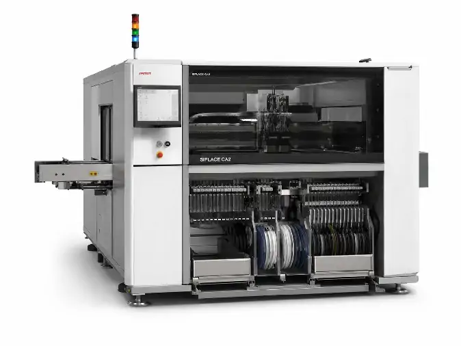
The ASMPT SIPLACE CA4 is a configurable chip-assembly and placement platform designed for conventional SMD placement, direct die attach from wafers, flip-chip placement and mixed production. Its four-position material configuration can combine SIPLACE Wafer Systems and feeder changeover tables, allowing the machine to support feeder-supplied components and wafer-supplied dies within one production platform.
For an initial inquiry, send the product and substrate dimensions, die and SMD information, wafer format, required placement process and target output. If a specific pre-owned CA4 is already available, include its nameplate, photographs, position layout, placement-head information, wafer-system records, conveyor details and software information. The actual machine configuration must be confirmed before published platform specifications are applied to one offered unit.
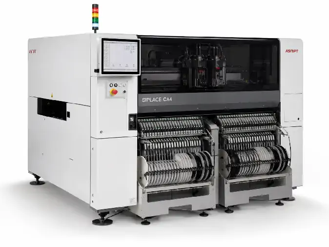
ASMPT SIPLACE CA4 Machine Information
| Produttore | ASMPT |
|---|---|
| Modello | SIPLACE CA4 |
| Tipo di apparecchiatura | Configurable chip-assembly and SMT placement platform |
| Processi supportati | SMD placement, direct die attach, flip-chip placement and mixed SMD-and-die production |
| Material Configuration | Up to four combined SIPLACE Wafer System and feeder changeover-table positions |
| Published SMD Placement Speed | Up to 126,500 components per hour with four feeder changeover tables |
| Published Flip-Chip Placement Speed | Up to 46,000 components per hour with four SIPLACE Wafer Systems |
| Published Die-Attach Speed | Up to 30,000 components per hour with four SIPLACE Wafer Systems |
| Published Placement Accuracy | Up to ±10 µm at 3 sigma for specified wafer-lane processes, up to ±12 µm at 3 sigma for specified panel-lane processes and ±15 µm at 3 sigma for published SMD placement |
| Flip-Chip Die Size | Published range from 0.5 mm to 15.0 mm |
| Die-Attach Die Size | Published range from 0.8 mm to 15.0 mm, with smaller sizes available for selected configurations on request |
| SMD Component Range | Published capability from very small SMDs, including 0201 metric, up to 15.0 mm depending on the installed head and process |
| Minimum Silicon Die Thickness | 50 µm for published wafer processes |
| Minimum Bump Size | 25 µm for published flip-chip applications |
| Minimum Bump Pitch | 50 µm for published flip-chip applications |
| Dimensioni del wafer | 4-inch to 12-inch wafers |
| Gestione dei wafer | Horizontal SIPLACE Wafer System with wafer-map support, automatic wafer exchange and multi-die capability |
| Placement Force | Touchless placement and programmable force from approximately 0.5 N to 15.0 N, depending on the installed placement head |
| Dipping Capability | Linear Dipping Unit LDU 2 X with programmable application speed and dwell time when installed |
| Published Flux Viscosity Range | 3,000 to 100,000 cps |
| Published Flux Height Accuracy | ±5 µm |
| Tipi di substrato | FR4, ceramics, flex circuits, boats, 8-inch or 12-inch wafers and other compatible carriers |
| Substrate Thickness | Published range from 0.3 mm to 4.5 mm |
| Substrate Range | Approximately 50 mm × 50 mm to 685 mm × 650 mm, depending on conveyor configuration |
| Conveyor Options | Flexible dual, single-lane, wafer-lane and panel-lane conveyors |
| Transport Modes | Synchronous and asynchronous transport |
| Published Machine Dimensions | Approximately 3,778 mm × 2,100 mm × 1,835 mm with SIPLACE Wafer System |
| Published Power Supply | 3 × 400 VAC, ±5%, 50/60 Hz |
| Condizione | Pre-owned chip-assembly and placement equipment |
| Configurazione attuale | Confermato in base alla specifica macchina disponibile |
| Ambito di fornitura | In base al preventivo e all'elenco delle attrezzature confermato |
| Supporto | Initial configuration review, fault analysis, component matching and repair discussion |
| Spedizione | Imballaggio per l'esportazione e spedizione in tutto il mondo. |
Four-Position Material Configuration
The SIPLACE CA4 is built around a configurable four-position arrangement. Each position can be assigned to a SIPLACE Wafer System or a feeder changeover table, and the total combination can be adapted to the material flow required by the product.
A feeder-intensive assembly may use more feeder-table positions, while a product with several wafer-supplied die types may require more wafer-system positions. Two machines carrying the same CA4 model name can therefore support different production flows. The position layout of the offered machine should be documented before its process value is assessed.
SMD Placement, Direct Die Attach and Flip-Chip Placement
The CA4 platform can perform conventional SMD placement, direct die attach from wafers and face-down flip-chip placement. These processes can be used separately or combined in a mixed production flow where bare dies and standard SMDs are placed on the same substrate.
The published maximum rates represent different machine configurations. The SMD benchmark is based on a machine equipped with four feeder changeover tables, while the direct-wafer figures are based on four SIPLACE Wafer Systems. One machine cannot be assumed to deliver all maximum figures simultaneously.
SIPLACE Wafer System and Die Handling
The horizontal SIPLACE Wafer System supports wafer-map processing, automatic wafer exchange and multi-die production. Published wafer support extends from 4-inch to 12-inch formats, with stretcher and hoop-ring handling options available for compatible wafer frames.
Die compatibility depends on wafer mounting, die dimensions, die thickness, pickup surface, ejector setup, wafer stretch, vision recognition and the required placement process. The official platform data lists a minimum silicon thickness of 50 µm and a direct-wafer component range extending up to 15 mm for applicable configurations.
Placement Heads, Accuracy and Force
CA4 systems may use different placement-head combinations according to the required speed, component range, force and process. Published performance includes accuracy classes up to ±10 µm at 3 sigma for specified wafer-lane applications and ±15 µm at 3 sigma for SMD placement, but the applicable result depends on the installed head, conveyor, component, placement position and calibration condition.
Low-force and touchless handling functions are relevant to thin or sensitive dies. Published force control extends from touchless placement and approximately 0.5 N up to 15 N depending on the head. The usable force range and required tooling should be confirmed for the offered machine rather than inferred from the platform brochure.
Linear Dipping and Flux Application
The optional LDU 2 X Linear Dipping Unit supports programmable flux application speed and dwell time for compatible flip-chip and die-attach processes. Published data lists a flux-viscosity range of 3,000 to 100,000 cps and flux-height accuracy of ±5 µm.
A dipping unit must still be matched to the actual material, deposit thickness, die size, process temperature and downstream joining route. Flip-chip placement should not be treated as proof of thermocompression bonding capability, because heating, force, atmosphere and bonding time may require separate equipment or process modules.
Substrate and Conveyor Compatibility
Published substrate support includes FR4, ceramics, flex circuits, boats, wafers and other compatible carriers. The platform can use flexible dual, single-lane, wafer-lane and panel-lane conveyors, with synchronous or asynchronous transport.
The published substrate range extends from approximately 50 mm × 50 mm to 685 mm × 650 mm and from 0.3 mm to 4.5 mm in thickness, depending on the conveyor. Before purchase, confirm the installed conveyor, usable width, flow direction, board support, clamps, carriers and upstream or downstream interfaces.
Compatibilità di prodotto e di processo
A useful CA4 review should begin with the material flow and product format rather than the model number alone. Basic project information should include:
Die dimensions, thickness, surface condition and wafer diameter
Number of wafer-supplied die types used in each product
SMD package sizes, quantities and feeder requirements
Substrate, panel, wafer or carrier dimensions and thickness
Die-attach, flip-chip, dipping and downstream joining sequence
Required placement accuracy, takt time and acceptance method
For a replacement project, also document the current CA4 position layout, placement heads, wafer systems, feeder tables, conveyor, software, programs, tooling and factory interfaces that must remain compatible.
Available SIPLACE CA4 Configuration and Delivery Scope
Individual ASMPT SIPLACE CA4 machines may differ in their four-position allocation, placement heads, SIPLACE Wafer Systems, feeder changeover tables, wafer stretchers, hoop-ring hardware, ejectors, dipping units, conveyors, cameras, software, licenses, computers, feeders, nozzles and tooling. Before purchase, the actual machine should be reviewed against the intended wafer, die, SMD, substrate and production process. The final delivery scope is based only on the quotation and confirmed equipment list; wafer hardware, feeders, tools, carriers, computers, software, documentation, spare parts and external utility equipment are included only when specifically stated.
Ricezione, avvio e controllo iniziale del campione.
The SIPLACE CA4 should be inspected and tested in stages before valuable wafers, dies or production substrates are introduced.
Inspect the packing, machine frame, cabinets, conveyors, four material positions, placement heads, wafer systems, cameras, guards and control equipment.
Photograph any impact marks, loose assemblies, damaged cables or displaced wafer and placement components before moving the machine.
Compare the received machine, wafer systems, feeder tables, heads, conveyors, dipping equipment, tools and accessories with the confirmed delivery list.
Confirm the electrical supply, grounding, compressed air, vacuum, exhaust, network and environmental requirements of the actual machine.
Start the controller and record all alarm messages before resetting the system or changing machine data.
Run the conveyors, placement axes, feeder interfaces and wafer-handling mechanisms without production material.
Use representative non-production samples to check pickup, die ejection, vision recognition, optional dipping, placement and substrate transport.
Verify the software, product programs, wafer maps, traceability and line interfaces required by the intended process.
A powered-on dry cycle confirms basic motion but does not prove wafer pickup stability, vision performance, placement accuracy or production readiness. When the purchase decision depends on a particular product, the demonstration and acceptance criteria should be defined around that product.
Placement Faults, Wafer Handling and Parts Support
Pickup failures, die rotation, vision rejects or unstable placement can involve wafer tension, ejector setup, pickup tooling, contamination, lighting, calibration, recipe settings or die-surface conditions. Feeder and substrate faults may involve reel setup, feeder communication, conveyor alignment, board support, carriers or warped products.
Software issues may involve program files, licenses, wafer-map orientation, coordinate conversion, component libraries, computer condition or external interfaces. Record the alarm message and the exact stage at which the problem occurs before resetting the machine. Photos of the wafer, die, substrate, tooling and alarm screen, together with a short operating video where available, can provide a practical starting point for review.
Our team can assist with initial fault analysis, component identification, replacement-part matching and repair discussion. Related cameras, sensors, motors, drivers, boards, cables, vacuum parts, feeder components, wafer-handling assemblies, ejector parts, nozzles and product fixtures can also be checked where available.
Domande frequenti
Can the ASMPT SIPLACE CA4 place SMDs and bare dies in the same process?
Yes. The CA4 platform supports feeder-supplied SMD placement and direct placement from wafers in a mixed production flow when the required feeder tables, wafer systems, heads and process modules are installed.
Does every SIPLACE CA4 have four wafer systems?
No. The four positions can be assigned to SIPLACE Wafer Systems or feeder changeover tables in different combinations. The installed position layout must be confirmed on the actual machine.
Does every CA4 achieve the published 126,500 cph SMD speed?
No. That figure is a published benchmark for a configuration using four feeder changeover tables. Actual output depends on the heads, component mix, feeder arrangement, substrate, placement pattern, machine condition and acceptance method.
Can the CA4 process dies larger than 8 mm?
The published platform data lists applicable flip-chip and die-attach ranges extending up to 15 mm. The minimum and maximum size still depend on the installed head, tooling, wafer presentation, die thickness and process.
Is any CA4 suitable as a direct replacement for another CA4?
No. Machines may differ in position allocation, placement heads, wafer systems, feeder tables, conveyor, software, licenses and tooling. A replacement machine should be compared with the current line position by position and interface by interface.
Can you assist with CA4 alarms, configuration questions or replacement parts?
Yes. Send the full model information, alarm message, machine and module photographs and a short operating video where available. We can assist with initial configuration review, fault analysis, component matching and repair discussion.
Contact Us About the ASMPT SIPLACE CA4
Send the die and wafer information, SMD list, substrate dimensions, planned placement process, target accuracy and production requirement. If a specific machine is already available, include its nameplate, four-position layout, placement-head information, wafer-system records, conveyor details, software information, photographs and operating evidence. We will review the basic application first and continue with the required machine configuration, tooling, replacement-parts or repair details afterward.