The ASMPT SIPLACE CA4 and SIPLACE CA2 both combine conventional SMT placement with direct placement of bare dies from sawn wafers. That shared capability can make them look like two versions of the same machine, but their architecture and production emphasis are different.
The CA4 V2 is a four-gantry platform derived from the SIPLACE X-Series concept. It offers high feeder-based SMT capacity, multiple SIPLACE Wafer System positions and a broad component window. The CA2 uses two CP20 placement heads and a newer multi-wafer material-flow concept that puts more emphasis on fast die attach, flip-chip placement and frequent switching among wafer-supplied die types.
The useful question is therefore not which model is universally better. It is whether the product is dominated by tape-fed SMDs, direct-wafer dies, larger components, many die types or a particular line-integration requirement.
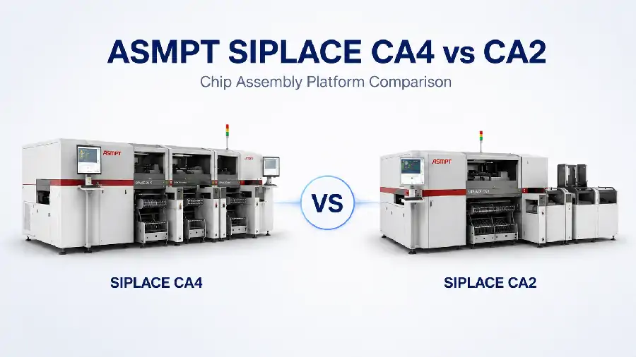
CA4 vs CA2 at a Glance
The CA4 is usually the stronger starting point for a feeder-intensive product that still needs direct-wafer capability. Its platform data shows substantially higher benchmark SMT throughput and support for up to four combinations of wafer systems and feeder changeover tables.
The CA2 is more clearly optimized around wafer-to-substrate material flow. Its official data lists higher die-attach and flip-chip rates than the legacy CA4 platform figures, together with multi-wafer handling, die buffering and single-die traceability.
| Production Priority | Platform to Evaluate First | Reason |
|---|---|---|
| High volume of tape-fed SMDs | SIPLACE CA4 | Its SMT benchmark is higher and the platform provides greater feeder-oriented capacity. |
| High-volume die attach directly from wafer | SIPLACE CA2 | Its architecture emphasizes die buffering and parallelized direct-wafer placement. |
| Frequent changes among many wafer-supplied die types | SIPLACE CA2 | The wafer system is designed to hold up to 50 different wafers and exchange them rapidly. |
| Components or dies above the CA2 documented 8.2 mm range | SIPLACE CA4 | Applicable CA4 head and process configurations extend to 15 mm. |
| Replacement of an installed CA4 process | Evaluate both | Existing heads, wafer systems, programs, tooling and conveyor arrangements may matter more than model age. |
This is an initial direction, not a configuration approval. A real selection must still match the die map, feeder count, substrate format, joining route and required cycle time.
Both Platforms Bridge SMT and Direct-Wafer Placement
Both machines can place SMDs supplied from feeders and bare dies supplied through wafer-handling equipment. Depending on the installed process modules, they can support die attach, face-down flip-chip placement or mixed assembly in which dies and SMT components are placed within one production flow.
This hybrid role is relevant to System-in-Package production, multi-die modules, embedded components and selected wafer- or panel-level packaging tasks. The main benefit is not simply that two component types fit inside one machine. It is that material presentation, placement and traceability can be organized around one line concept.
Flip-chip placement should still be separated from the joining process. Placing a bumped die face-down does not by itself establish thermocompression bonding capability; heat, force, atmosphere, dwell time and downstream process requirements must be evaluated independently. Readers comparing placement and bonding routes can continue to the advanced packaging and flip chip equipment solutions or the flip chip bonder equipment category.
Architecture and Published Performance
The CA4 figures below come from ASMPT's official SIPLACE CA technical data for the CA4-generation platform, while the CA2 figures come from ASMPT's February 2026 brochure. The documents cover different machine generations, configurations and benchmark methods. These values show the documented performance direction rather than a normalized head-to-head test.
| Comparison Point | SIPLACE CA4 V2 | SIPLACE CA2 |
|---|---|---|
| Platform architecture | Four-gantry X-Series-based chip assembly platform | Two SIPLACE CP20 placement heads |
| Material configuration | Up to four combined SIPLACE Wafer System or feeder-table positions | Up to two Multi Wafer Systems plus 10 × 8 mm tape feeder tracks, or up to 80 × 8 mm feeder positions |
| SMT placement benchmark | Up to 126,500 cph with four feeder changeover tables | Up to 76,000 cph |
| Flip-chip placement from wafer | Up to 46,000 cph with four wafer systems | Up to 51,000 cph |
| Die attach from wafer | Up to 30,000 cph with four wafer systems | Up to 54,000 cph |
| Accuracy direction | Up to ±10 µm at 3 sigma for specified wafer-lane processes; ±15 µm at 3 sigma for SMD placement | 20 µm, 15 µm or 10 µm at 3 sigma, selected by placement position and component shape |
| Direct-wafer die range | 0.5–15 mm for flip chip and 0.8–15 mm for die attach, with smaller die-attach sizes available on request | 0.3 mm × 0.3 mm to 8.2 mm × 8.2 mm |
| Tape-fed component range | From 0201 metric or 01005, depending on head, up to 15 mm | From 0201 metric to 8.2 mm × 8.2 mm |
| Wafer handling emphasis | Automatic wafer exchange, multi-die support and wafer sizes from 4 to 12 inches | Up to 50 different wafers, with the overview stating a swap time below 13 seconds and the technical table listing 13 seconds |
The accuracy rows also need separate interpretation. CA4 V2 data distinguishes wafer-lane, panel-lane and SMD conditions, while CA2 allows different accuracy classes to be assigned by placement position and component shape. On CA2, the available substrate area changes with the selected accuracy class. A quoted 10 µm value is therefore a process condition, not a universal machine setting that applies across the full working area.
Wafer capability is expressed differently as well. CA4 data emphasizes wafer formats from 4 to 12 inches and the ability to install several SIPLACE Wafer Systems. CA2 documentation emphasizes the number of different wafers available to the exchange system and the speed of changing between them. A line needing several wafer sources in rapid sequence may benefit from CA2's material organization, while a process built around particular wafer sizes, several simultaneous wafer-system positions or a legacy SWS setup may still point toward CA4.
The pattern is clearer than any single number. CA4 allocates more of the platform to feeder-based SMT capacity and a wider component window. CA2 gives more weight to direct-wafer throughput, die buffering and multi-die material handling.
The speed values should not be combined into a simple overall machine rate. Product output will also be affected by die ejection, wafer exchange, vision, dipping, placement pattern, substrate indexing and the ratio between wafer-fed and tape-fed components.
The Production Mix Determines the Better Fit
Feeder-Intensive Products Favor the CA4 Architecture
A package with many passive components and only a small number of bare dies may use more of the CA4's strengths. Its higher SMT benchmark and four-position material architecture can support a production balance in which conventional placement remains the largest part of the cycle.
The installed heads still matter. C&P20 M2 and CPP M configurations do not have the same component window or process behavior. A machine described only as “SIPLACE CA4” is not specific enough for a product match.
Wafer-Intensive and Multi-Die Products Favor the CA2
The CA2 becomes more attractive when direct-wafer dies account for a large share of placements or when the product uses several die types. ASMPT attributes its direct-wafer rates to die buffering and process parallelization, while the wafer exchange concept supports rapid switching among many wafer sources.
This does not mean every mixed product should move to CA2. A configuration with two Multi Wafer Systems retains 10 tape-feeder tracks. If the bill of materials needs substantially more feeder positions, a separate high-speed SMT machine or a different division of work may be more efficient.
Component Size Can Decide the Comparison Early
The CA2 CP20 range ends at 8.2 mm × 8.2 mm. The CA4 V2 data extends to 15 mm with the applicable head and process configuration. A product containing larger dies or SMDs may therefore rule out CA2 before throughput is considered.
Width is only the first boundary. Die thickness, bump pitch, pickup surface, placement force, substrate support and dipping requirements can still determine whether a component inside the nominal size range is practical.
CA2 Is a Different Production Balance, Not a Smaller CA4
The two-head CA2 should not be read as a reduced version of the four-gantry CA4. It shifts machine capacity toward direct-wafer flow, traceability and modern multi-die handling. CA4 remains relevant where broader component handling, feeder density or continuity with an installed CA4 process is more valuable.
For an existing line, replacement planning should compare the complete method: current feeder and wafer hardware, validated programs, tooling, substrate transport, software interfaces and operator experience. A newer platform direction does not automatically make migration the lower-risk choice.
A Practical Selection Sequence
A productive comparison starts with the product rather than the machine brochure:
Separate every placement into tape-fed SMD, tray-fed component or wafer-supplied die.
Count the number of die types and wafer changes required by the product family.
Check the largest and smallest components against the applicable head range.
Define substrate dimensions, warpage, conveyor arrangement and required accuracy area.
Map the dipping, flip-chip, die-attach and downstream joining sequence.
Estimate cycle time from the real placement mix rather than adding brochure maximums.
This sequence usually reveals whether the line needs one hybrid machine or a division of work. CA2 may concentrate on wafer-supplied dies while another placement machine handles a feeder-heavy SMD load. CA4 may be more suitable where one platform must retain substantial conventional SMT capacity alongside wafer processing.
Line balance is especially important when one process step runs much slower than the others. A higher die-placement rate has limited value if wafer replenishment, flux dipping, substrate loading or downstream reflow sets the takt time. Conversely, a high SMT benchmark may not improve output when die ejection and wafer recognition dominate the cycle. The comparison should therefore end with a product-level time study, even when the platform data already points clearly toward one model.
What to Verify on an Actual CA4 or CA2
When the decision concerns a used or already identified machine, verify the items that can change the comparison outcome:
| Verification Area | What to Confirm | Why It Changes the Decision |
|---|---|---|
| Machine identity | Full model, version, serial number and manufacturing record | CA, CA4 and CA4 V2 descriptions should not be treated as automatically identical. |
| Placement and material modules | Heads, wafer systems, feeder tables, dipping units and conveyors | The installed combination determines whether the platform comparison applies. |
| Vision and calibration | Cameras, inspection options and available accuracy evidence | A brochure accuracy class does not describe current machine condition. |
| Software and interfaces | Software release, licenses, wafer-map support and factory communication | Line integration can be limited by the delivered software package. |
| Application demonstration | Wafer loading, die pickup, recognition, dipping, placement and transport | A powered-on dry cycle does not verify the complete production process. |
For an identified machine, the review should also cover its service history, included tooling, available test evidence and final delivery scope. These unit-specific details go beyond the platform comparison but may ultimately determine whether the machine is suitable.
ASMPT SIPLACE CA4 vs CA2 FAQ
Which machine has the higher documented placement speed?
CA4 V2 has the higher SMT benchmark, while CA2 has the higher documented direct-wafer die-attach and flip-chip rates. The figures come from different platform documents and are not a normalized cycle-time test.
Can both platforms place SMDs and bare dies?
Yes. Both support feeder-supplied SMD placement and direct placement from wafers when equipped with the required material and process modules.
Does CA2 replace CA4 for new SiP projects?
Not in every case. CA2 is attractive for wafer-intensive and multi-die production, but CA4 may remain the better fit for feeder-heavy assemblies, larger components or lines built around an existing CA4 configuration.
What information is most useful for choosing between them?
Provide the die and SMD list, material source for each component, wafer count, substrate format, joining sequence, accuracy requirement and target cycle time. For a specific machine, add its head, wafer-system, conveyor, software and vision configuration.
For deeper CA2 platform details, continue to the ASMPT SIPLACE CA2 specifications and applications guide. To discuss an identified machine or project, send the product and configuration information through the semiconductor equipment inquiry page.
Conclusion: Choose between the ASMPT SIPLACE CA4 and CA2 by following the product's material flow. CA4 is the stronger initial direction for feeder-intensive SMT, broader component handling and continuity with a four-gantry CA process. CA2 is better aligned with high-volume direct-wafer placement, frequent multi-die changes and die-level traceability. Documented rates narrow the shortlist, but the final match comes from the real placement mix and installed machine configuration.