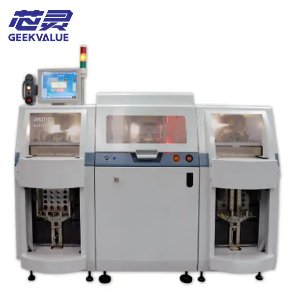
ASMPT MPHENIX Trim and Form System
Pre-owned ASMPT MPHENIX trim and form system. Ask about machine condition, installed tooling, delivery scope, replacemen...
Trim and form systems convert molded leadframe strips into finished semiconductor packages by removing tie bars and dam bars, forming package leads, separating devices and transferring the completed output for inspection or packing. Browse available automatic systems and match the machine, tooling and handling configuration to your package drawing.
The machine setup must match the leadframe drawing, package geometry, tooling and required output format.
PACKAGE-SPECIFIC SETUPReview the current Besi Fico and ASMPT equipment collection. Product pages describe the model platform; the actual tooling, handling modules, controls and included package setup must still be confirmed for each available machine.
Pre-owned ASMPT MPHENIX trim and form system. Ask about machine condition, installed tooling, delivery scope, replacemen...
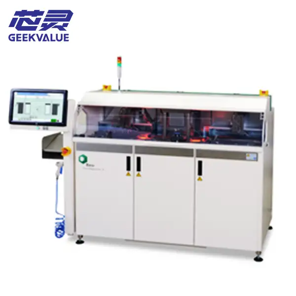
Pre-owned Besi Fico Compact Line-X trim and form system. Ask about installed modules, tooling, machine condition, parts,...
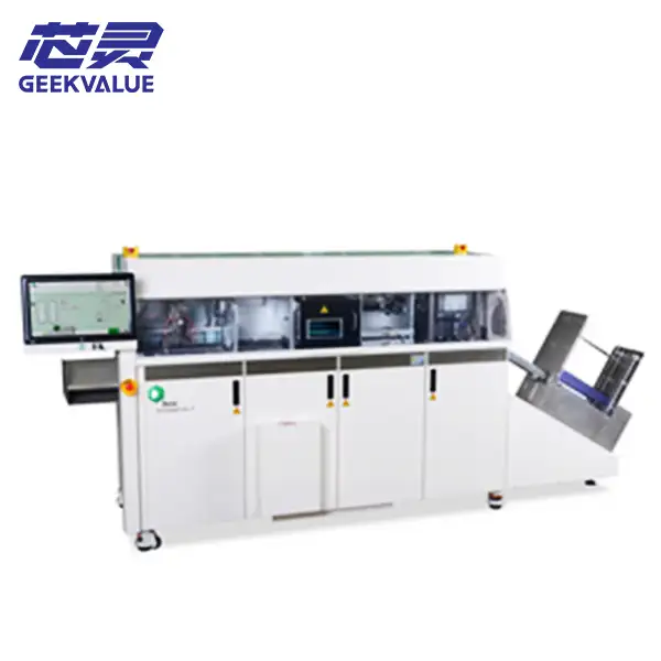
Pre-owned Besi Fico Compact Line-P trim and form system for power semiconductor packages. Ask about configuration, tooli...
A trim and form project starts with the required finished geometry—not with a generic equipment specification. The package outline, lead pitch, lead length, stand-off, coplanarity target and singulation method determine the tooling and machine setup.
For a replacement machine or a new package introduction, share the package drawing, leadframe strip drawing, sample strip and desired output handling. These details make it possible to review whether an existing platform and tool set can be reused or whether a new conversion is required.
Identify the molded package family, body dimensions, lead count and strip layout.
Confirm the required cut length, bend profile, stand-off and dimensional tolerance.
Define how the devices leave the strip and whether the line requires additional deflash or inspection.
Match the finished package handling to downstream inspection, marking, test or packing.
An automatic trim and form line may combine several mechanical finishing operations. The exact order and included stations vary by package, tooling and platform.
Magazines, trays or other handling modules introduce the molded leadframe strip and establish orientation.
The trim tool removes tie bars, dam bars or other temporary leadframe connections required during molding.
Package leads are bent or shaped to the specified final geometry using the matched form tooling.
Devices are singulated from the strip or transferred through the package-specific separation module.
Optional vision, sorting and output handling transfer accepted packages to tube, tray, bulk or the next process.
The press, handling platform and controls provide the production base. The actual package capability comes from the trim die, form tooling, grippers, tracks, change kits and inspection setup installed on the machine.
Confirm the installed tool set, package compatibility, maintenance history and availability of replacement inserts or wear parts.
The form tool must match the required bend profile, stand-off, coplanarity and lead dimensions—not only the package name.
Review the input strip format, loader, gripper, transfer path and the required tube, tray, bulk or inline output arrangement.
Check installed cameras, monitoring options, software version, recipe storage, quality checks and factory-interface requirements.
The examples below are selection directions, not universal machine specifications. Final compatibility must be verified from the package drawing and actual tooling.
| Package direction | Typical selection focus | Questions to confirm |
|---|---|---|
| Gull-wing packages | Lead geometry and coplanarity Forming consistency, pitch control, lead protection and stable output handling become central. | Body size, lead count, pitch, stand-off, final bend profile and allowable coplanarity. |
| Small-outline and fine-lead packages | Tool condition and changeover control Fine lead spacing increases sensitivity to tool wear, alignment and package handling. | Strip layout, lead pitch, package thickness, tooling history and inspection requirement. |
| Discrete and power packages | Force, robust tooling and package-specific output Thicker leads or larger package structures may require a different press and handling direction. | Leadframe material, lead thickness, package body, forming force, separation route and output format. |
| High-density leadframe strips | Material flow and production stability Loader capacity, strip transfer, dual-press or modular configurations can influence sustained output. | Strip density, magazine capacity, target volume, inspection points, MTBA expectations and line integration. |
Verify the exact platform, build information, machine photos and control generation.
List every trim die, form tool, gripper, track, nest, change kit and spare insert included.
Confirm loader, magazines, transfer mechanism, sorting and finished-package output arrangement.
Review maintenance history, mechanical play, tool condition, sensors, pneumatics and safety systems.
Check installed software, licenses, camera functions, inspection options and factory communication.
Where possible, define the sample material, inspection criteria and evidence required before shipment.
A platform may be mechanically operational but still be unusable for your product if the required tool set, package change kit or output handling is missing.
For used Besi Fico, ASMPT or another legacy system, ask for a clear inventory of the machine, tooling, spare parts, software and installed options. The quotation should describe the actual supplied configuration, not only the original model capability.
Trim and form is one part of package finalization. Use these pages to review the upstream package body process, downstream identification and the wider finalization line.
Review molding and encapsulation equipment used to create the protected package body before mechanical trim and form.
Explore Molding Machines →Compare package marking systems for device ID, lot codes and traceability after the mechanical package form is established.
Explore Laser Marking →See molding, trim and form, marking and electroplating equipment within the wider backend finalization workflow.
View the Finalization Solution →These answers help define the project before a model- and tooling-level review.
Start with the package drawing, leadframe strip drawing, sample strip, package family, lead geometry, required singulation route, target output format and production volume. If replacing an existing system, also provide the current model, tooling numbers and machine photos.
Some platforms support multiple package families through tooling and change-kit conversions, but compatibility is not automatic. The press capacity, strip handling, tool envelope, track, gripper, inspection and output modules must all support the new package setup.
No. Singulation is the separation of individual packages, while trim and form also covers removal of temporary leadframe connections and shaping the package leads. Some automatic systems integrate all three operations in one line.
Verify the exact model, serial number, press and control condition, installed trim and form tooling, loaders, magazines, tracks, grippers, output modules, vision options, software, spare parts and maintenance history. A sample-run or package-specific acceptance plan is preferable where practical.
Yes. The drawing is a useful starting point. Include the leadframe strip format, target volume, current process, required output handling, preferred equipment condition and destination country so the available platform and conversion route can be reviewed.
It commonly follows molding or encapsulation for leadframe-based packages and may connect with deflash, inspection, laser marking, plating, electrical test or final packing depending on the package and factory process.
Share the package family, leadframe strip, final lead geometry, output format, required condition, quantity and destination. We will review the available system, tooling scope and practical sourcing route.