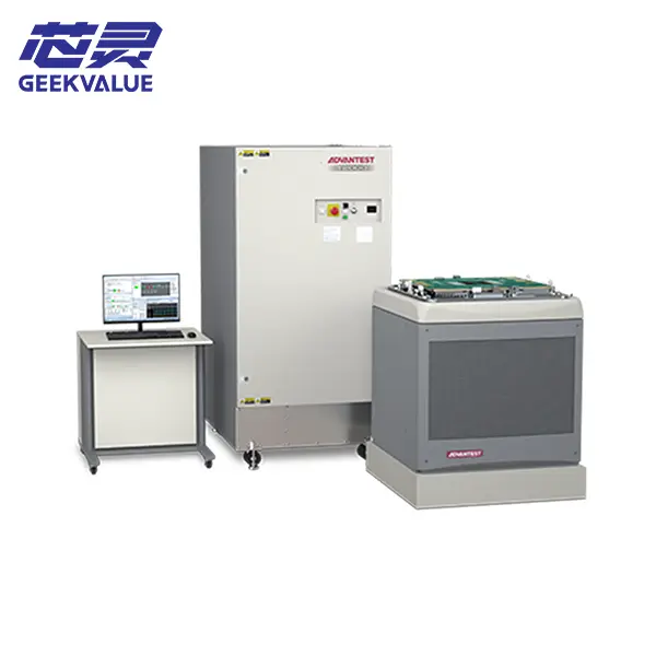
Advantest T2000 Modular SoC and Mixed-Signal Semiconductor Test System
Advantest T2000 modular semiconductor test system for SoC, digital, mixed-signal, PMIC, automotive d
Semiconductor automatic test equipment applies programmed electrical stimuli to an IC, measures the response and determines whether the device meets its specification. Browse available ATE systems for SoC, digital, mixed-signal, PMIC and related applications, then match the tester configuration to your device, test stage and production target.
Review the current equipment collection, then confirm the installed modules, test head, software, calibration status and interface hardware of the actual system being quoted.
Advantest T2000 modular semiconductor test system for SoC, digital, mixed-signal, PMIC, automotive d
An ATE system is not selected only by pin count or brand. The required tester resources come from the electrical functions inside the target IC.
Digital speed, analog accuracy, device power, high-current capability, image capture and RF resources may all change the correct platform and module combination.
Review a Device Test RequirementSuccessful wafer sort or final test depends on the complete signal and mechanical path. The tester, interface hardware, prober or handler, software and production data flow must work as one cell.
Positions the wafer die or packaged device, controls contact and may provide temperature conditioning.
Probe card, load board, socket, pogo assembly and cables carry stimulus and measurements.
Digital, analog, power and parametric modules provide the electrical resources required by the DUT.
Patterns, limits, timing, measurement sequences and binning logic execute the device test plan.
Results move into yield analysis, traceability, MES and production-control systems.
Buying an ATE mainframe without the correct interface and software can leave the system unusable for the target product. Confirm the complete test cell before comparing quotations.
Explore Test & Handling Solutions →The electrical tester may support both stages, but the mechanical interface, contact hardware, parallelism and production flow are different.
Electrical tests are performed directly on die before dicing. The cell requires the correct probe card, wafer map flow, chuck conditions and prober interface.
Packaged ICs are presented to sockets, electrically tested and sorted by result. The cell requires matching handler, HIFIX, contactor, load board and temperature setup.
ATE buyers often compare purchase price first, but production economics are usually driven by test time, parallel site count, retest rate, contact stability and system utilization.
A lower-cost tester can become expensive if it lacks the channels, instruments or interface capacity needed for the intended multi-site plan. An oversized configuration can also leave capital idle.
The practical target is a system configuration that provides the required coverage and throughput without paying for instruments the device will not use.
A used semiconductor tester cannot be evaluated from the platform name alone. Ask for a complete hardware, software and interface inventory tied to the actual machine.
The value of a used ATE system depends on the installed resources and whether they match the target test program.
Confirm frame type, slot count, test-head model, air or liquid cooling and power requirements.
Request exact digital, analog, PMU, DPS, high-power or image-capture module lists.
Check that the controller, operating system and software support the installed instruments.
Identify what is included and what must be designed or sourced separately for the DUT.
Review calibration dates, power-on status, diagnostic records and previous application.
Clarify test-head support, export packing, rigging, installation and post-delivery calibration.
Use these links when the requirement extends beyond the tester itself or when the test stage still needs to be defined.
Review how wafer probing, final-test handling and electrical test resources work together from CP testing through packaged-device sorting.
Read the Semiconductor Test Guide →Answers to common questions about automatic test equipment, test-cell integration and used-system configuration.
It applies programmed digital, analog, power or parametric stimuli to an integrated circuit, measures the response and compares the results with test limits. The exact devices it can test depend on the installed instruments, software and DUT interface.
The ATE generates and measures electrical signals. The test handler moves packaged devices, controls their test temperature, places them into the contactor and sorts them according to the result returned by the tester.
Potentially, yes. A suitable tester can connect to a wafer prober for CP testing or a handler for final test, but each stage requires different interface hardware, contact solutions, software flow and production integration.
Start from the device functions. General SoC platforms can combine digital, analog and power resources, while memory, RF/mmWave or high-power applications may require specialized instrumentation or a dedicated platform.
Their mainframes, test heads, module quantities, revisions, software licenses, calibration status, interface hardware and included accessories may be very different. A complete configuration list is required before comparing value.
Send the target device or application, preferred platform or model, test stage, required digital or analog resources, expected site count, current interface information, preferred machine condition, destination and schedule.
Share the semiconductor application, required test resources, wafer-sort or final-test stage, preferred brand or model, condition and destination. We will review the available system configuration and the missing parts of the test cell.