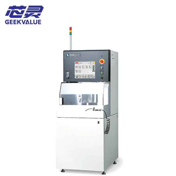
DISCO DAD3241 Dicing Saw
DISCO DAD3241 dicing saw for wafer and substrate cutting. Confirm the spindle, chuck table, installed options, machine c...
A dicing saw machine uses a high-speed precision spindle and thin blade to separate semiconductor wafers, compound materials, glass, ceramic substrates and packaged devices into individual parts. Browse available wafer dicing saws and compare the workpiece size, material, automation level, spindle arrangement and cut-quality requirements for your production process.
The same dicing saw is not automatically suitable for every wafer or package. Material hardness, thickness, surface structure and mounting method affect the blade, spindle load, coolant, feed speed, chuck or frame and the achievable edge quality.
Confirm wafer diameter, thickness, street width, frame and required die-edge quality.
Hard or brittle materials may need a different blade, spindle power and process window.
Chipping, blade loading, coolant and thicker workpieces become central selection factors.
Package singulation may require panel handling, multi-workpiece alignment or dual-spindle output.
Review the current dicing saw collection, then open the individual model page for its stated capabilities. The actual machine year, spindle, work table, software, accessories and operating condition should be confirmed from the equipment being quoted.
Need a DISCO, ACCRETECH, ADT or another wafer dicing saw model not listed here? Send the target model and process requirement so we can check sourcing options.
DISCO DAD3241 dicing saw for wafer and substrate cutting. Confirm the spindle, chuck table, installed options, machine c...
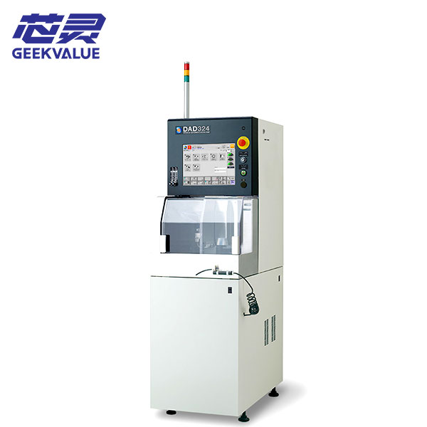
DISCO DAD324 blade dicing saw for wafer and substrate cutting. Review machine identity, process fit, test scope, tooling...
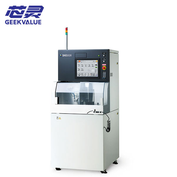
DISCO DAD3230 dicing saw for wafer singulation and precision cutting. Check the spindle, chuck table, options, condition...
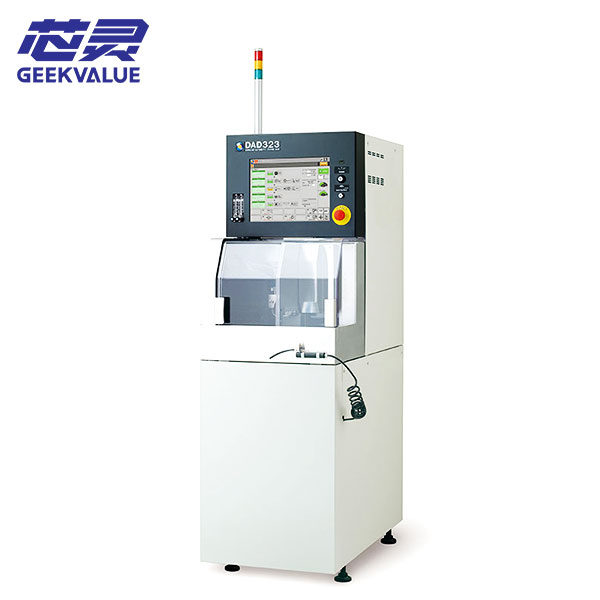
DISCO DAD323 blade dicing saw for wafer and substrate singulation. Review lifecycle status, machine checks, process inpu...
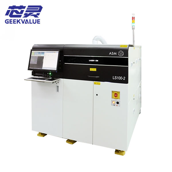
ASM LS100-2 laser cutting machine for semiconductor equipment applications. Confirm the process configuration, laser sou...
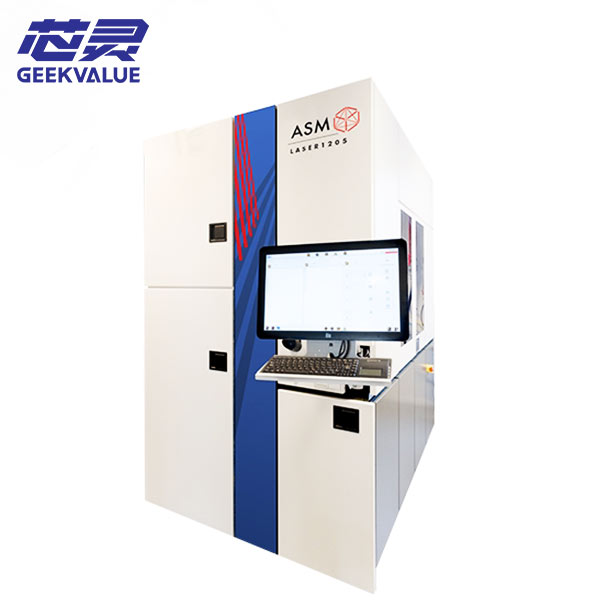
Explore ASMPT ALSI LASER1205 laser dicing machine for semiconductor wafer separation and grooving. Learn about multi-bea...
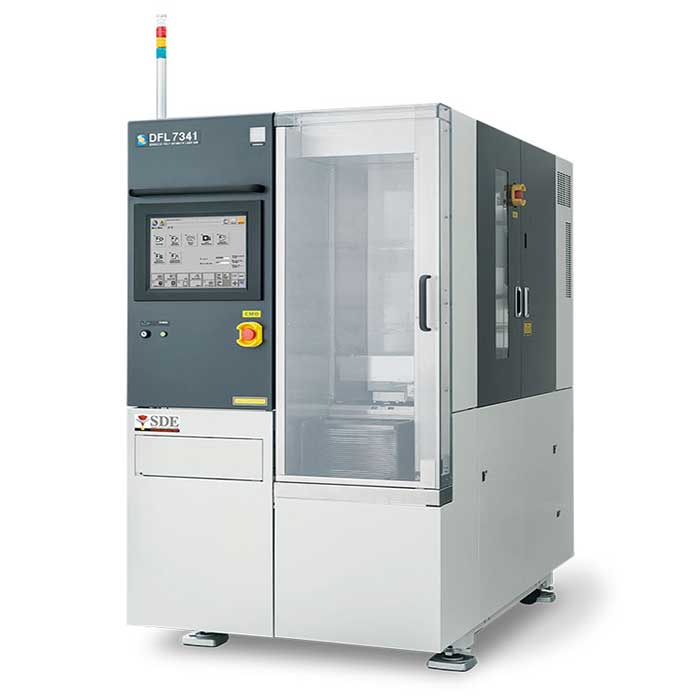
Explore DISCO DFL7341 wafer cutting machine with Stealth Dicing™ technology. Learn about laser wafer cutting, SiC, sapph...
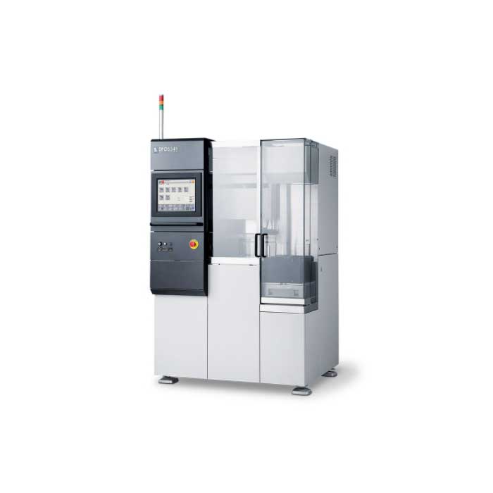
Explore DISCO DFD6341 fully automatic dicing saw for semiconductor wafer cutting. Learn about dual spindle technology, 8...
The right automation level depends on whether the priority is process flexibility, operator control, repeat production, integrated handling or continuous output.
Fully automatic systems are selected when wafer or panel loading, alignment, cutting, cleaning, drying and unloading need to operate as a coordinated production sequence. They are usually evaluated by handling compatibility, throughput, vision, recipe control and production stability rather than spindle speed alone.
Repeat production and medium-to-high volume semiconductor or package singulation.
Cassette, frame, panel or workpiece handling and the cleaning/drying route.
Automation condition, software, robot, aligner, spindle and included peripherals.
Fully automatic wafer dicing saw and automatic semiconductor dicing machine.
Useful for varied workpieces, engineering production and operations that still require operator loading or setup while retaining programmed alignment and cutting.
Compare stage size, chuck or frame support, vision, recipe capability and operator workflow.Manual or compact systems may suit laboratories, R&D, small-volume work, process trials and special materials where flexibility matters more than automated handling.
Operator skill, alignment method, spindle condition and safety features become especially important.Spindle arrangement changes throughput and process flexibility. Laser dicing is a separate route that may be evaluated when blade contact, kerf, water use or material behavior makes conventional blade dicing less suitable.
A practical route for varied products, development, lower-to-medium volume and processes that prioritize flexibility or simpler maintenance.
Confirm spindle power, blade diameter, work area, cut depth and material range.Parallel or facing dual-spindle systems can increase output or support multi-step cutting, but only when the workpiece flow and process recipe justify the added configuration.
Compare simultaneous cutting strategy, alignment, dressing, spindle condition and handling cycle.Blade dicing remains widely used for silicon, packages, glass and ceramic. Laser ablation or stealth dicing may be considered for specific materials, narrow streets or dry processing requirements.
Do not select by kerf alone; die strength, heat effect, debris, throughput and downstream separation also matter.Chipping, edge cracks, blade marks, kerf variation and contamination are not solved by buying the highest-speed machine. They depend on the complete relationship between material, blade, spindle, feed, coolant, mounting and cleaning.
A stable wafer dicing process requires more than positioning accuracy. Blade specification, spindle runout, chuck flatness, tape support, cutting water, feed speed, cut depth and dressing condition all influence die-edge quality and usable throughput.
Material brittleness, blade exposure, feed conditions, vibration and tape support can change top-side and backside chipping.
Street width, vision recognition, axis accuracy and blade thickness determine how safely the cut remains inside the intended lane.
Resin, metal, glass and ceramic can load the blade differently, making dressing strategy and spindle load monitoring important.
Cutting debris and residual moisture must be controlled before inspection, die separation or downstream assembly.
You do not need a complete technical specification before contacting us. Start with the product and production information you already know. We can use it to narrow the work area, spindle, handling, blade and automation requirements.
Material, wafer or workpiece size, thickness and whether it is mounted on frame, tape, panel or fixture.
Required work area, table or chuck format, blade route and suitable machine family.
Full cut, half cut, grooving, package singulation, street width and target die size.
Cut depth, spindle and blade requirements, alignment method and process configuration.
Expected volume, product mix, changeover frequency and required automation level.
Manual, automatic or fully automatic handling and single- or dual-spindle options.
Preferred manufacturer or model, new/used condition, quantity, destination and project schedule.
Current equipment availability, actual configuration, included accessories, packing and delivery scope.
Use these links when your project also requires wafer mounting before cutting, cleaning after cutting or a broader wafer-processing equipment review.
Review dicing tape and frame mounting systems when wafer support, alignment and tape condition affect the cutting process.
Explore wafer mounting equipment → After dicingCompare post-dicing scrub, spray, rinse and drying systems for particle and cutting-debris removal.
View wafer cleaning equipment → Equipment categoryReview related wafer mounting, thinning, cleaning and singulation equipment across the process flow.
Browse the equipment category → Technical readingContinue with process-selection, equipment-buying and semiconductor production articles.
Read related guides →These questions cover the points buyers most often need to clarify before selecting a wafer dicing saw or package singulation machine.
Depending on the spindle, blade, table, coolant and process configuration, dicing saws may process silicon wafers, compound semiconductors, glass, ceramic, sapphire, electronic substrates and packaged devices. Material support must be confirmed for the actual machine and blade process.
An automatic saw may automate alignment and programmed cutting while still relying on the operator for loading or transfer. A fully automatic system can integrate loading, alignment, cutting, cleaning, drying and unloading. Exact terminology varies by manufacturer, so the handling sequence should be checked.
Dual spindles may improve throughput or support multi-step cutting, but the benefit depends on workpiece size, cut pattern, recipe, handling cycle and product mix. A dual-spindle system is not automatically the best option for frequent changeover or low-volume work.
Chipping is affected by material, blade type and exposure, feed speed, spindle condition, cut depth, mounting support, coolant and dressing. The complete process should be reviewed rather than changing a single parameter in isolation.
Blade dicing is widely used for wafers, packages, glass and ceramic. Laser ablation or stealth dicing may suit certain narrow-street, hard-material or dry-process requirements. Compare kerf, heat effect, debris, die strength, throughput and downstream separation.
Confirm the complete model, serial number, year, spindle type and condition, chuck or table, axes and vision, software, handling modules, cleaner and dryer, blade accessories, maintenance history, utilities and the scope of any refurbishment or test.
Not always. Blades, flanges, dressing boards, frames, fixtures, chucks, coolant components and other process tooling should be itemized in the quotation because requirements vary by workpiece and process.
Send the material, workpiece size and thickness, mounting format, cut type, street or die size, automation requirement, preferred model or brand, required condition, quantity and destination. Available information is enough to begin the review.
Tell us the material, workpiece size, thickness, cut method, automation requirement, preferred condition and destination. We will review available dicing saw machines and the configuration required for your project.