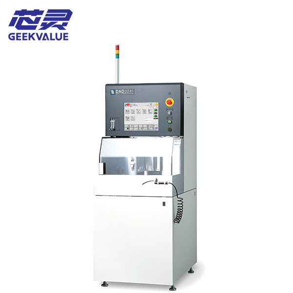
The DISCO DAD3230 is a compact automatic dicing saw designed for precision cutting of compatible semiconductor wafers, electronic components, glass, ceramics and other materials. It uses a single spindle and supports workpieces up to 6 inches, while larger square or rectangular workpieces require the applicable special configuration.
For an initial inquiry, send your current dicing-saw model, clear photos of the wafer or workpiece and a short description of the required cutting process or current machine problem. Detailed blade, material and cutting-street information can be reviewed later when necessary.
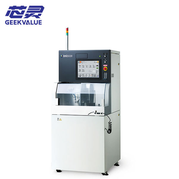
DISCO DAD3230 Machine Information
| Manufacturer | DISCO |
|---|---|
| Model | DAD3230 |
| Equipment Type | Automatic single-spindle dicing saw |
| Maximum Workpiece Size | Up to Φ6 inches under the standard model specification |
| Special Workpiece Support | 150 × 150 mm or 220 × 160 mm workpieces with the applicable special configuration |
| X-Axis Cutting Range | 160 mm standard or 220 mm with the applicable optional configuration |
| Y-Axis Cutting Range | 162 mm |
| Feed Speed Range | 0.1–500 mm/sec |
| Spindle Output | 1.5 kW |
| Spindle Speed Range | 3,000–40,000 min⁻¹ |
| Alignment Functions | Automatic alignment with autofocus and automatic kerf-check functions according to the model specification |
| Machine Dimensions | Approximately 730 × 900 × 1,670 mm |
| Machine Weight | Approximately 600 kg |
| Production Status | Discontinued by the manufacturer; DAD3231 is listed as the successor model |
| Condition | Pre-owned precision dicing equipment |
| Delivery Scope | Based on the quotation and confirmed equipment list |
| Shipping | Export packing and worldwide delivery |
Workpiece and Cutting Process Compatibility
The DAD3230 model capacity does not automatically confirm that an available machine can process every wafer, substrate or electronic component. Compatibility also depends on the workpiece material, dimensions, thickness, cutting-street width, required kerf, blade specification, spindle condition and holding method.
Only basic information is needed for the first discussion:
- Your current dicing-saw model if the DAD3230 will replace existing equipment
- Clear photos of the wafer, substrate or electronic component
- A close-up photo of the cutting street or current cutting result where available
- A short description of the required process or existing cutting problem
Detailed drawings, material data, street dimensions, blade specifications and cutting parameters can be reviewed later when the available machine appears relevant to the project.
Spindle, Blade and Alignment Setup
The DAD3230 uses a 1.5 kW spindle with a shaft-lock mechanism intended to simplify blade replacement. A low-expansion spindle was also available as an option to reduce spindle displacement caused by temperature changes.
Cutting quality depends on the blade material and thickness, spindle condition, flange, workpiece holding, alignment, cutting-water delivery and process settings. Existing blades, flanges or fixtures should not be assumed to fit the available machine without checking its actual spindle and table configuration.
DAD3230 Expandability and Available Configuration
The DAD3230 was designed with additional internal space for special applications and may differ between machines in worktable size, spindle type, alignment optics, cutting-water control, microscope configuration, transformer, UPS, fixtures and external utility equipment. Before purchase, the available unit should be reviewed to confirm whether its actual cutting and workpiece-holding setup is suitable for the intended material. The final delivery scope is based only on the quotation and confirmed equipment list; blades, flanges, fixtures, wafer frames, transformers, UPS units, chillers, water-treatment equipment and external utility systems are included only when specifically stated.
Receiving, Startup and Initial Cutting Trial
The DAD3230 should be inspected and tested in stages before valuable production workpieces are introduced.
- Inspect the packing, machine cabinet, spindle area, worktable, microscope, control panel and utility connections.
- Photograph any impact marks, loose components, damaged cables or displaced assemblies before moving the machine.
- Compare the received machine, blade flanges, fixtures, pumps and accessories with the confirmed delivery list.
- Check that the spindle, worktable, microscope and motion axes remain secured after transportation.
- Confirm the electrical supply, grounding, compressed air, vacuum, cutting water, cooling and drainage requirements.
- Start the controller and record all alarms before resetting the machine or changing cutting parameters.
- Check table movement, spindle rotation, alignment, autofocus, water flow and related safety functions without a production workpiece.
- After basic operation is stable, use a suitable blade and non-production sample for an initial cutting trial.
Inspect the cutting street before increasing feed speed or cutting depth. Repeat several cuts to check consistency, and stop testing if spindle vibration, abnormal noise, unstable alignment, water-flow problems or repeated alarms occur.
Cutting Results, Alarms and Parts Support
Chipping, excessive kerf, blade marks, incomplete cutting or unstable cutting depth may involve blade selection, spindle runout, flange condition, workpiece holding, alignment, feed speed, cutting depth or cutting-water conditions.
Position errors may also involve the worktable, microscope calibration, theta alignment, autofocus, encoder feedback or incorrect product data. The cutting result and machine condition should be reviewed together before process parameters are repeatedly changed.
Record the alarm message and the stage at which the problem occurs before resetting the machine. Photos of the blade, flange, workpiece, cutting street, chuck table and alarm screen, together with a short operating video where available, can provide a practical starting point for review.
Our team can assist with initial fault analysis, blade and component identification, replacement-part matching and repair discussion. Related spindles, motors, drivers, boards, sensors, cameras, cables, valves, pumps, water-system components and motion parts can also be checked where available. Because the DAD3230 has been discontinued, the availability of specific replacement parts should be confirmed for each repair requirement.
Frequently Asked Questions
Can the DISCO DAD3230 cut our wafer or electronic component?
This depends on the workpiece material, dimensions, thickness, cutting street, blade, spindle and holding configuration. Send workpiece and current cutting-result photos for an initial review.
Can every DAD3230 process 220 × 160 mm workpieces?
No. The extended workpiece size and 220 mm X-axis cutting range require the applicable special or optional machine configuration.
What is the difference between the DAD323 and DAD3230?
The DAD3230 is a separate model with a larger machine structure, a 1.5 kW spindle and greater provision for special configurations. Its specifications and accessories should not be copied from the DAD323.
Are blades, flanges and workpiece fixtures included?
Only blades, flanges, fixtures and related accessories listed in the quotation or confirmed delivery scope are included.
Can you assist with spindle alarms or poor cutting results?
Yes. Send the machine model, alarm information, blade and flange photos, close-up images of the cutting result and an operating video where available. We can assist with initial fault review, parts matching and repair discussion.
Contact Us About the DISCO DAD3230
Send your current dicing-saw model, wafer or workpiece photos and a short description of the required cutting process or equipment problem. We will review the basic application first and continue with the necessary blade, spindle, fixture, replacement-parts or repair details afterward.