Incoming Inspection
Confirm wafer identity, thickness, surface condition, warpage and the intended street layout before the wafer enters the cutting flow.
Key controlLot identity, visible damage, flatness and the approved cut plan.
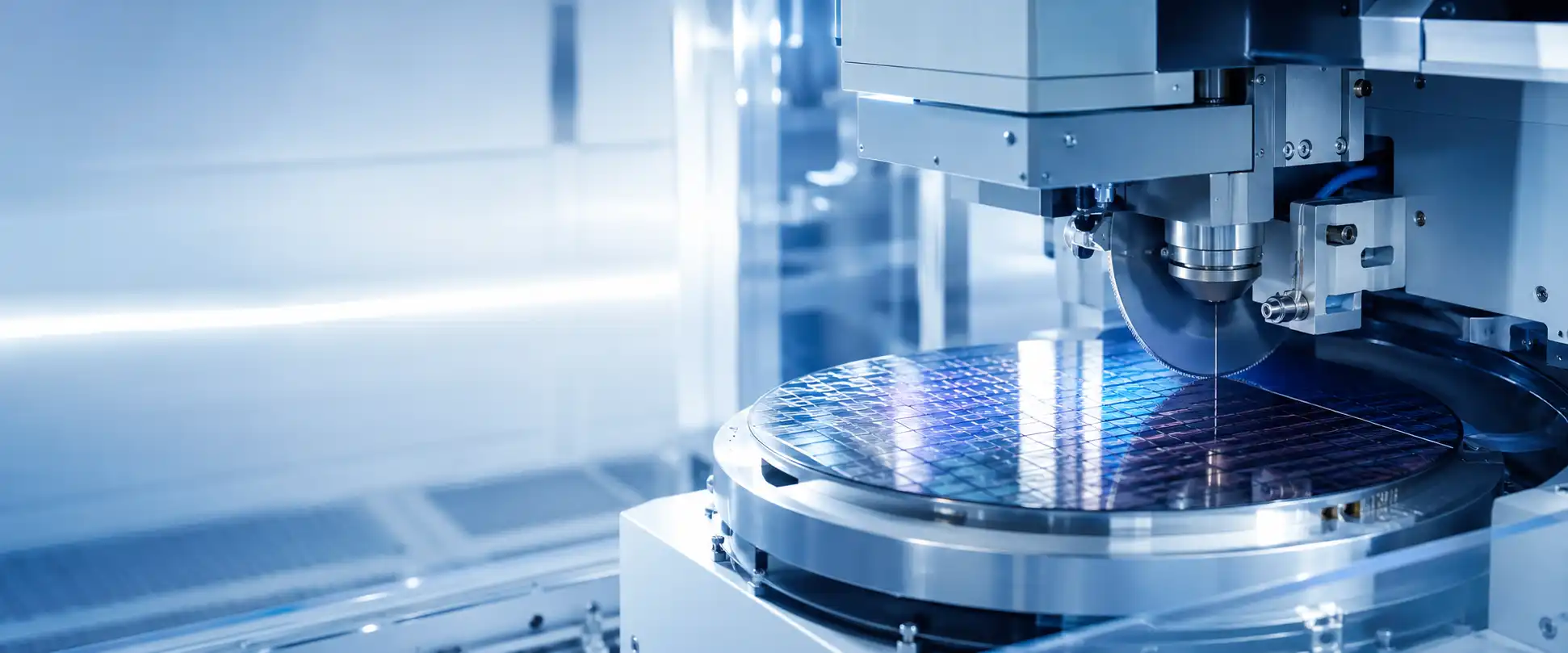
A reliable wafer cutting process begins before the blade enters the wafer. Mounting, alignment, cutting, cleaning and inspection form one connected sequence, and a weakness introduced at an early stage may only appear later as chipping, position drift, unstable cut depth or damaged dies. This page connects each stage with the equipment, parts and recovery options behind it.
Each stage has a clear purpose and a control point that should remain traceable. Recording the condition at each step makes it easier to identify where a defect was introduced instead of changing several settings after the final inspection.
Confirm wafer identity, thickness, surface condition, warpage and the intended street layout before the wafer enters the cutting flow.
Select and prepare the tape, frame and mounting materials that must hold the wafer through cutting and later release the separated dies.
Attach the wafer with clean, uniform support and controlled position so it can remain stable through alignment, cutting and cleaning.
Relate streets, edges or reference targets to the machine coordinate system before the cutting path is executed.
Run the established blade, depth, feed, spindle and water conditions while the workpiece remains supported and correctly positioned.
Remove cutting debris and residual water without disturbing the mounted wafer, tape or separated dies.
Review kerf position, chipping, die integrity, cleanliness and traceability before pickup or downstream assembly.
Localized backside chipping can begin with mounting support, while a position error found at final inspection may involve alignment, wafer movement or machine-axis stability. Preserve the sequence and recent-change history before adjusting the process.
Mounting defines how the wafer is supported, how accurately it can be located and how cutting load is transferred into the chuck-table system. A mounting defect may pass through alignment without an alarm and appear only after cutting.
A particle, wrinkle, trapped air pocket or uneven interface can let one region move or bend differently. The defect may then cluster in one area instead of appearing evenly across the wafer.
Adhesion, tension, thickness, aging and exposure history affect wafer movement during cutting and the way separated dies remain supported before pickup.
Off-center or angular mounting can reduce edge margin and interfere with chuck-table coverage, clamping, edge recognition or cut-limit control.
Tape and frame do not hold the wafer independently from the machine. Chuck-table cleanliness, vacuum stability, clamps and the vacuum path determine whether the mounted wafer stays fixed.
Thin wafers are more sensitive to particles, bending and transfer stress. Stable mounting reduces unnecessary mechanical variation before alignment and cutting begin.
Review local support, contamination, tape condition, frame position and the chuck-table interface.
Check mounting distortion, off-center placement, wafer movement and the selected alignment reference.
Inspect the mounted workpiece, tape, frame, chuck surface and vacuum path before treating it as a recipe-only issue.
Semimachine can begin from the stage where the process becomes unstable, then check the machine, workholding parts, cutting modules, vision components, utilities or replacement-equipment options that may be relevant to that stage.
Requests may involve chuck tables, frame clamps, fixtures, jigs, vacuum parts, ejectors and handling components. Matching begins with the machine model, frame format and part reference.
Available route: parts search, module repair or replacement workholding items.Camera, lighting, focus, sensor, cable, vision-board and alignment-module requests can be checked by machine model, module label, part number or clear installation photos.
Available route: part identification, repair or exchange of the affected module.Cutting-stage recovery may involve spindle assemblies, flanges, blade-detection parts, motors, drives, cooling components or related control items.
Available route: replacement part, module repair, exchange or backup stock.Pumps, valves, filters, nozzles, sensors, cleaning modules, dryers, loaders and transfer parts can be searched together with the machine fault or production requirement.
Available route: utility parts, handling repair or production-recovery support.When repair time, missing parts or machine condition makes recovery impractical, we can also check used wafer saws for the same model, related generation or compatible production format.
Available route: replacement machine, backup equipment or line-capacity expansion.The same request can include the machine, missing accessories, replacement parts, inspection information, export packing, international delivery and future spare-parts needs.
Available route: coordinated equipment, parts and shipment preparation.A useful inquiry connects the machine identity with the exact process stage, visible evidence and recent changes. It can also state whether the immediate requirement is technical review, a replacement part, module repair, backup equipment or a complete wafer saw.
These answers clarify the process sequence and how a stage-specific issue can connect to equipment, parts, repair or machine replacement.
The terms often overlap. Wafer dicing usually emphasizes separating a wafer into individual dies, while wafer cutting process can describe the wider sequence from incoming inspection and mounting through cutting, cleaning and final review.
It can contribute through uneven support, local movement, vacuum instability, trapped particles or height variation. The defect should still be reviewed together with the blade, spindle, alignment, water and machine condition.
Record where the defect appears, whether it is local or uniform, the process stage where an alarm occurs and any recent tape, blade, recipe, workpiece, maintenance or utility change. The sequence history is often more useful than the defect name alone.
Depending on the machine, requests may involve chuck tables, frame clamps, vacuum parts, spindles, flanges, cameras, sensors, pumps, valves, water and cooling parts, cleaning modules, handling systems, drives, boards and control components.
Send the machine model, affected stage, module label, connector view, installation position and several clear photos. A part number is preferred, but installation evidence can help narrow the search.
Yes. The same request can compare parts, module repair or exchange, backup stock and a used replacement wafer saw. The practical route depends on the specific machine, fault, available parts, configuration and production requirement.
Cutting debris and residual water can affect die surfaces, tape condition, inspection and downstream handling. Cleaning and drying should remove contamination without moving the mounted dies or weakening the support required before pickup.
Review kerf position, frontside and backside chipping, die integrity, cleanliness, cut depth, orientation and lot traceability. Defect location should be recorded so it can be connected with mounting, alignment, cutting or cleaning conditions.
Share the wafer saw model, process stage, workpiece format, visible evidence and the recovery direction you need. Semimachine can check technical support, machine-specific parts, module repair, backup equipment or a complete replacement wafer saw.