Workpiece and Workholding
Tape condition, frame support, chuck-table cleanliness, vacuum stability and workpiece flatness determine whether the wafer remains fixed during every cut.
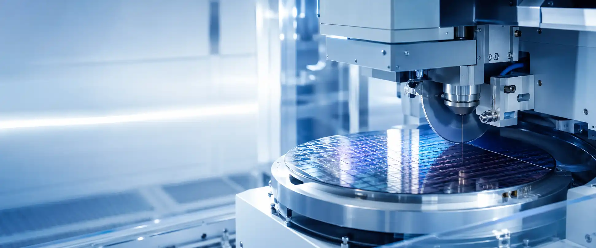
A stable dicing result depends on the combined condition of the workpiece, mounting, blade, spindle, motion, alignment, vacuum and water systems. Use the defect pattern and recent changes to narrow the likely cause, then connect the case with the relevant wafer saw part, repair route or replacement-equipment option.
Feed speed or spindle speed may be the easiest values to change, but they work inside a larger process window. A stable result requires the mechanical support, tooling, machine motion and utilities to remain consistent at the same time.
Tape condition, frame support, chuck-table cleanliness, vacuum stability and workpiece flatness determine whether the wafer remains fixed during every cut.
Blade specification, mounting accuracy, dressing condition and blade exposure influence cutting load, wear, straightness and edge quality.
Spindle condition, feed speed, cut depth, axis stability, alignment and kerf-check control must work together rather than being treated as unrelated settings.
Water flow, temperature and nozzle condition affect debris removal, blade condition and the thermal stability of the spindle and chuck-table system.
Chipping is often described as a blade or speed problem. In practice, the same visible defect can be produced by different combinations of support, tooling, load, temperature and machine condition. The useful question is not only “which setting changed?” but “which part of the process window stopped being stable?”
Foreign matter under the wafer, damaged or changed tape, unstable chuck-table vacuum, local warpage or incomplete frame support can allow small movement during cutting. The result may appear as irregular chipping that changes by location rather than a uniform defect along every street.
Grit size, bond, concentration, blade thickness, exposure and wear determine how the blade removes material. Flange contamination, mounting error, insufficient dressing or a damaged blade can add runout, deflection or unstable cutting load even when the programmed recipe has not changed.
Feed speed cannot be judged in isolation from spindle speed, blade condition and material. A process with too little effective load may not keep the blade cutting surface in the desired condition, while excessive load can increase deflection, wear, breakage risk or edge damage. Stable dicing requires a balanced operating window rather than one universally “safe” speed.
Cutting water removes debris and supports blade stability, while cooling water helps keep the spindle system thermally stable. Changes in flow or temperature can influence cutting position, depth and consistency through contamination, poor debris removal or thermal movement in the spindle and chuck-table system.
Alignment error, hairline offset, kerf-check drift, spindle-speed variation or axis vibration can move the cut away from the intended street or change the mechanical load from one cut to another. This is why defect photos should be reviewed together with alarm history, position data and the stage at which the problem appears.
May point toward particles, uneven support, tape condition, local vacuum loss or intermittent vibration.
First direction: inspect mounting, chuck-table contact and the affected wafer area.May suggest that the blade, flange, exposure, dressing condition or cutting-load balance no longer fits the workpiece.
First direction: compare the blade setup and the last known-good process condition.May involve alignment, thermal stability, spindle condition, axis feedback, table setup or water temperature.
First direction: review position data, trend over time and machine-side stability.When the issue begins after a new blade, tape, lot, recipe, maintenance action or replaced part, preserve the before-and-after evidence.
First direction: isolate whether the result follows the changed item or remains with the machine.Once the recent process changes and repeatable defect pattern have been recorded, the next step may be a machine-specific part, module repair, exchange option or another wafer saw. Semimachine can review these routes in the same inquiry instead of separating the process case from the equipment requirement.
Localized movement, abnormal blade load, repeated breakage or unstable depth may lead to checks around the cutting and workholding systems.
Kerf drift, focus changes, repeatability errors or machine alarms may involve cameras, sensors, drives, encoders, boards, cables or control modules.
When downtime, parts availability or machine condition makes one route uncertain, the same case can include repair communication and used-equipment checking.
A machine model or alarm code alone rarely explains a dicing-quality problem. A useful case combines the equipment identity, defect distribution, recent changes and the point where the result becomes unstable. The same request can also state whether you need troubleshooting direction, a part, module repair or a replacement wafer saw.
These answers focus on how to interpret a process change before selecting a part, repair route or replacement machine.
No single feed value guarantees lower chipping. Feed speed interacts with spindle speed, blade specification, blade condition, material, cut depth and workholding. A lower value may reduce load in one process but may not solve a blade, vacuum, mounting or machine-stability issue.
Yes. Axis vibration, spindle condition, flange mounting, chuck-table vacuum, alignment, water stability or another machine condition may contribute. The defect pattern and machine history should be reviewed before replacing parts or changing several recipe values at once.
Depending on the symptom, inquiries may involve the spindle, flange, chuck table, vacuum components, cameras, sensors, water or cooling parts, drive modules, control components or handling accessories. Availability must be checked against the exact machine and part reference.
Replacement may be considered when the required repair is impractical, downtime is becoming difficult to support, important parts are hard to source or additional capacity is needed. The current machine model and required process should be compared with the actual available equipment.
Dressing exposes the cutting surface and helps restore the blade condition required by the qualified process. Incomplete, excessive or inconsistent dressing can change cutting load, wear behavior, kerf appearance and chipping. Dressing conditions should be reviewed together with the blade specification, material and machine history.
Yes. Unstable flow, blocked nozzles, contamination, incorrect temperature or poor debris removal can affect blade condition, spindle stability and the workpiece surface. Water-related evidence should be reviewed together with the defect location and any recent utility or maintenance change.
Possible causes include alignment changes, camera or lighting instability, spindle or axis movement, thermal drift, chuck-table condition, vacuum variation and recipe or calibration changes. Compare the position trend, affected streets and machine events before changing several settings.
Send the wafer saw model, workpiece material and thickness, tape and frame, blade specification, feed, spindle speed, cut depth, water conditions, defect photos, recent changes and any alarm or operating video. This helps separate a process issue from a machine, part or workholding problem.
Share the wafer saw model, workpiece, blade information, defect pattern and recent changes. Semimachine can check the relevant machine-specific parts, repair or exchange direction, and used-equipment options for production recovery when needed.