Wafer dicing equipment for blade and laser semiconductor cutting
Blade, Laser and Advanced Dicing Technologies

Wafer Dicing Equipment Types and Cutting Technologies

Compare wafer dicing equipment by cutting method, material, wafer format, street width, edge-quality target and production flow. Semimachine supplies blade dicing saws and laser dicing systems, and helps factories match the required process with available machines, model-specific parts and practical delivery support.

Blade Dicing Saws Laser Dicing Systems Wafer and Substrate Processing Automatic and Semi-Automatic Equipment
Equipment Overview

What Is Wafer Dicing Equipment?

The equipment category includes several cutting technologies. The correct choice depends on the material and result required, not only on the wafer diameter or machine brand.

Wafer dicing equipment is used to create controlled grooves or separate wafers, packages and selected substrates into individual devices. Depending on the application, the cutting mechanism may be a high-speed abrasive blade, a laser process, internal laser modification, plasma etching or another qualified singulation method. The equipment must also control alignment, workholding, cutting position, debris, cleaning and inspection.

Cutting MethodBlade, laser, stealth, plasma and scribe-based approaches create the cut in different ways.
Workpiece ControlFrames, tape, chuck tables, fixtures and handling keep the material stable throughout the process.
Position and InspectionVision, alignment, focus and kerf inspection functions help maintain the required street position.
Factory IntegrationUtilities, loading, cleaning, software and surrounding equipment affect installation and production use.
Equipment names do not guarantee process compatibility. The selected platform should be checked against the actual material, thickness, die layout, kerf target, cut depth, throughput and quality requirement.
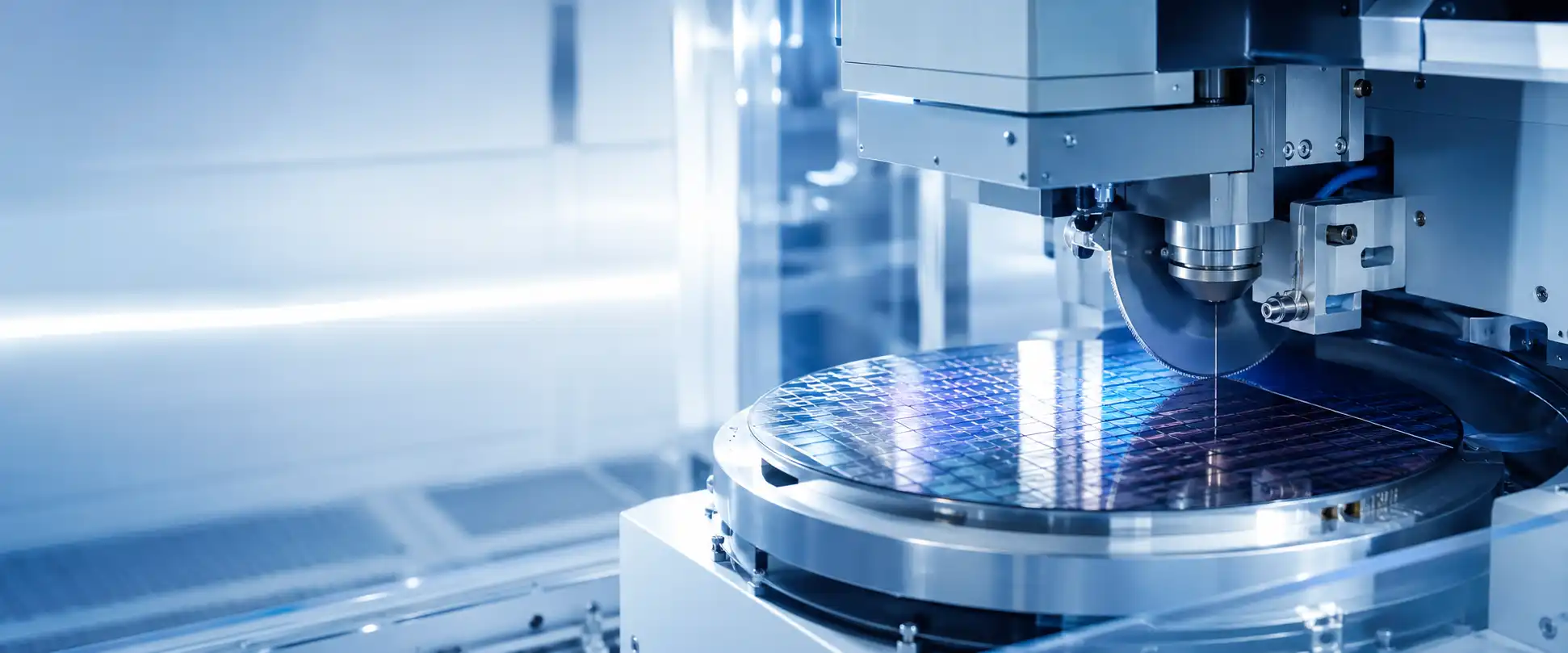
Cutting Technology Comparison

Main Types of Wafer Dicing Equipment

Each technology uses a different cutting mechanism and creates different requirements for workholding, process control, contamination management and downstream handling.

01

Blade Dicing Saw

A high-speed spindle drives a thin abrasive blade through the wafer or substrate while the machine controls alignment, feed, depth and cooling water.

  • Established semiconductor production platform
  • Full cut, grooving and step-cut processes
  • Single- or dual-spindle configurations
View blade dicing saws →
02

Laser Dicing System

Laser equipment uses a controlled optical process for grooving, ablation, full cutting or another qualified material-removal route.

  • Non-contact energy delivery
  • Application-specific laser source and optics
  • Material and heat-affected-zone evaluation
View available laser systems →
03

Stealth Dicing Equipment

A focused laser forms a modified layer inside a suitable wafer before controlled separation, reducing the need for conventional surface kerf removal.

  • Internal material modification
  • Requires compatible material and thickness
  • Separation and tape expansion must be controlled
Discuss the application →
04

Plasma Dicing Equipment

Plasma dicing separates exposed streets through an etching process and can support narrow streets or batch processing in qualified applications.

  • Requires suitable mask and wafer preparation
  • Dry process without a rotating blade
  • Process flow differs from conventional saw dicing
Review process requirements →
05

Scribe and Break Equipment

Scribing creates a controlled line before mechanical separation. It can be used for selected brittle materials and device structures.

  • Mechanical or laser scribing routes
  • Break quality depends on material behavior
  • Fixture and separation control are important
Send material information →
06

Integrated Dicing Automation

Automatic handling connects loading, identification, alignment, cutting, cleaning, drying and unloading into a controlled production flow.

  • Cassette, frame or workpiece handling
  • Recipe control and traceability options
  • Throughput and line-interface matching
Compare machine configurations →
Technology Selection

Compare the Process Before Comparing the Machine

A practical equipment decision starts with the workpiece and quality target. Technology advantages only matter when the complete process can be qualified for the device and factory flow.

  • Confirm material and layer structure.
  • Define street width and die geometry.
  • Set acceptable chipping and heat influence.
  • Check contamination and cleaning limits.
  • Match throughput and automation needs.
Equipment TypeCutting PrincipleCommon StrengthsImportant Conditions
Blade Dicing SawA rotating abrasive blade mechanically removes material along the programmed street.Established production methods, visible kerf control, broad machine availability and multiple cut formats.Blade selection, spindle condition, mounting, vacuum, feed, cooling water and debris control.
Laser Ablation or GroovingFocused laser energy removes or modifies material from the surface along the cutting path.Non-contact energy delivery, flexible pattern control and selected narrow-street applications.Material absorption, laser source, optics, heat influence, debris and process qualification.
Stealth DicingA laser forms an internal modified layer before the wafer is separated along the prepared line.Reduced conventional surface kerf and potential advantages for suitable thin or brittle wafers.Material transparency, thickness, focus depth, internal layer control and separation method.
Plasma DicingExposed street material is removed through a controlled dry etching process.Batch processing potential, narrow streets and no rotating blade in qualified flows.Masking, wafer preparation, plasma compatibility, etch uniformity and factory process integration.
Scribe and BreakA mechanical or laser scribe creates a controlled weakness before separation.Simple separation route for selected brittle structures and materials.Scribe quality, material behavior, fixture design, breaking force and edge consistency.
Application Requirements

Match Wafer Dicing Equipment to the Material and Device

Different workpieces place different demands on the cutting mechanism, mounting, cooling, debris control, inspection and downstream handling.

01 / SILICON

Silicon IC Wafers

Established blade dicing processes are widely used for silicon devices with qualified streets, frames, tape and cleaning conditions.

Check wafer diameter, thickness, street width, die size and cut format.
02 / POWER

SiC, GaN and Power Devices

Hard, brittle or high-value materials may require careful evaluation of blade wear, laser interaction, chipping and throughput.

Send the full material and layer structure before selecting the process.
03 / MEMS

MEMS and Sensor Wafers

Cavities, delicate structures and contamination-sensitive surfaces can make mounting, water and cleaning control especially important.

Identify exposed structures, coatings and restrictions on liquid processing.
04 / OPTICAL

Glass and Optical Substrates

Brittle transparent materials may use blade, laser, stealth or scribe-based routes depending on the structure and edge requirement.

Confirm transparency, thickness, coatings and acceptable edge condition.
05 / CERAMIC

Ceramic and LTCC Materials

Ceramic workpieces can require suitable blades, fixtures, cooling and feed control to manage wear and edge damage.

Provide material grade, dimensions, thickness and required separation result.
06 / PACKAGE

Packages and Substrates

Strip, panel and package singulation may need dedicated fixtures, handling and process controls beyond standard circular-wafer equipment.

Confirm format, encapsulant, substrate, unit layout and production flow.
07 / THIN WAFER

Thin and Back-Ground Wafers

Thin wafers place greater demands on tape support, workholding, warpage control, cut depth and post-dicing handling.

Include final thickness, carrier method and die-pickup requirements.
08 / SPECIALTY

Specialty and R&D Workpieces

Small batches or unusual materials may favor flexible loading, recipe access and fixture options over maximum automation.

Start from sample dimensions, material behavior and the result to be evaluated.
Available Equipment

Blade and Laser Wafer Dicing Equipment

Browse current blade dicing saws and laser processing systems. Open a product to review the listed model, then contact us to confirm the actual machine, installed configuration, condition, accessories, inspection information and delivery availability.

The required equipment may not be displayed. Send the manufacturer, complete model, existing-machine nameplate or process requirement so additional inventory and sourcing options can be checked.

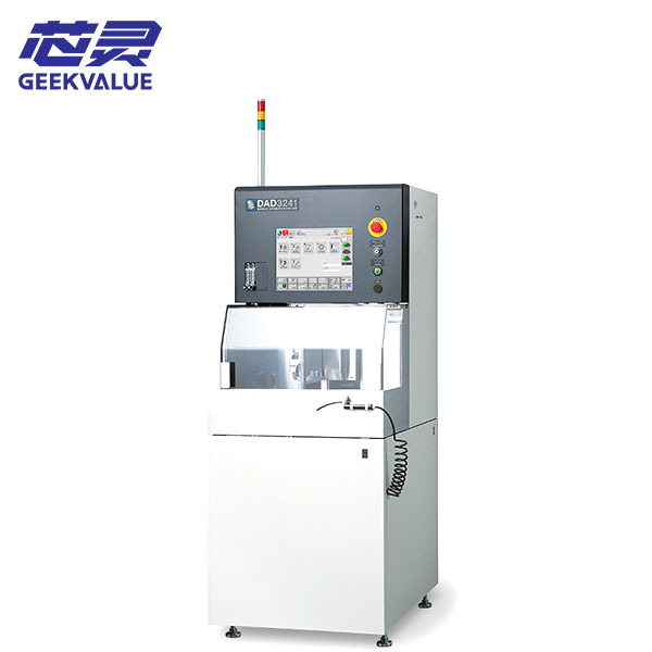
DISCO DAD3241 Dicing Saw
Blade Dicing Saw

DISCO DAD3241 Dicing Saw

DISCO DAD3241 dicing saw for wafer and substrate cutting. Confirm the spindle, chuck table, installed options, machine c...

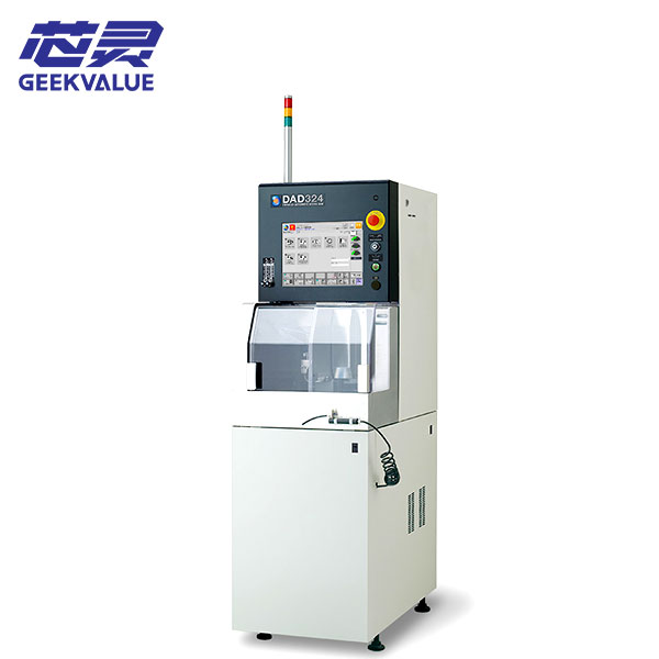
DISCO DAD324 Dicing Saw
Blade Dicing Saw

DISCO DAD324 Dicing Saw

DISCO DAD324 blade dicing saw for wafer and substrate cutting. Review machine identity, process fit, test scope, tooling...

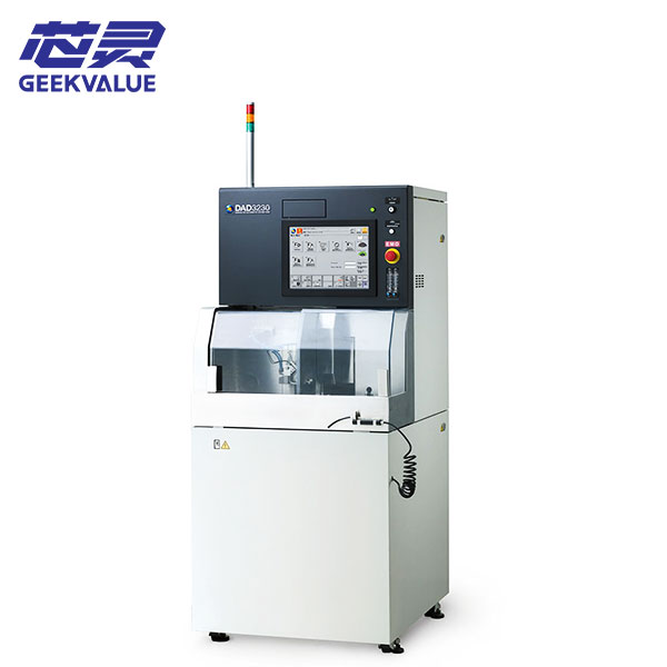
DISCO DAD3230 Dicing Saw
Blade Dicing Saw

DISCO DAD3230 Dicing Saw

DISCO DAD3230 dicing saw for wafer singulation and precision cutting. Check the spindle, chuck table, options, condition...

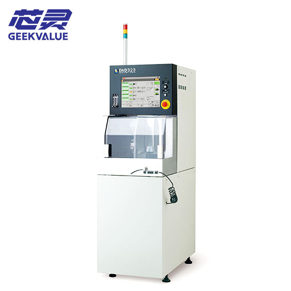
DISCO DAD323 Dicing Saw
Blade Dicing Saw

DISCO DAD323 Dicing Saw

DISCO DAD323 blade dicing saw for wafer and substrate singulation. Review lifecycle status, machine checks, process inpu...

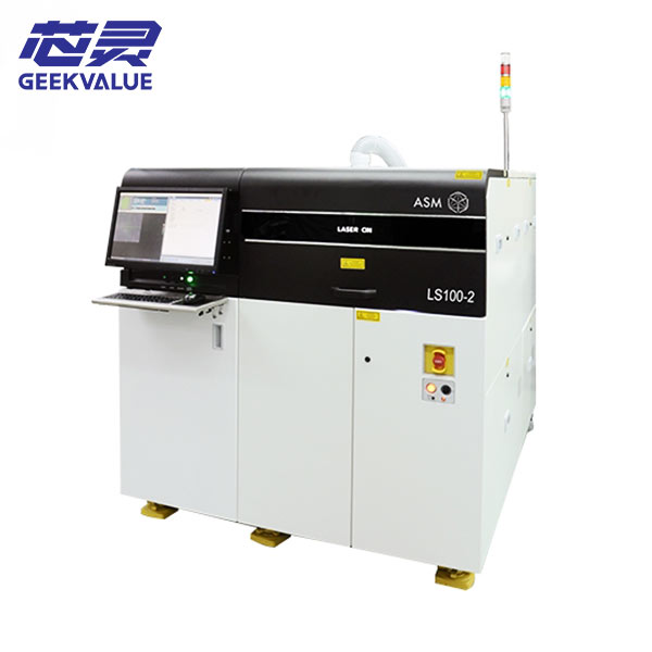
ASM LS100-2 Laser Cutting Machine
Blade Dicing Saw

ASM LS100-2 Laser Cutting Machine

ASM LS100-2 laser cutting machine for semiconductor equipment applications. Confirm the process configuration, laser sou...

Machine Systems and Functions

Compare the Complete Equipment Platform

The cutting technology is only one part of the equipment decision. Workholding, alignment, utilities, inspection and automation determine how the process operates in production.

01

Cutting Module

Spindle, blade, flange and water delivery for blade equipment, or laser source, optics, focus and process head for laser systems.

02

Workholding

Chuck table, vacuum, frame, tape, fixture, clamp and support method for the specific wafer or substrate format.

03

Vision and Alignment

Camera, lighting, pattern recognition, street alignment, focus and position-correction functions.

04

Motion and Depth Control

Axis performance, feed, cut depth, focus position, repeatability and recipe-controlled movement.

05

Cleaning and Debris Control

Cooling water, spray, extraction, cleaning, drying and contamination-control functions required by the process.

06

Inspection

Kerf check, cut-position review, focus verification, defect observation and process-monitoring options.

07

Automation and Handling

Manual loading, frame handling, cassette transfer, identification, automatic cleaning and unloading functions.

08

Utilities and Software

Power, air, water, cooling, exhaust, footprint, recipes, traceability and surrounding-line interfaces.

Replacing an existing machine?

Send the full nameplate and identify the functions that must remain compatible. The search can begin with the exact model and widen to related configurations only when necessary.

Review Machine Selection
Equipment Matching and Supply

Turn the Process Requirement into a Machine Specification

Semimachine can begin with a target model, an installed machine, a wafer sample, a drawing or a required cutting result. The request can include current equipment, unlisted model searches, machine-specific parts, inspection information, packing and international delivery.

Exact ModelSearch the same manufacturer, model and installed production format.
Process-Based MatchUse material, dimensions, street, cut type, quality and throughput.
Capacity AdditionFind another machine that fits the existing operator and line workflow.
Production RecoveryCheck parts, repair, module exchange or replacement equipment together.
Workpiece Information

Material, Format and Mounting

Provide material, wafer or panel dimensions, thickness, frame, tape, fixture and any warpage or handling concerns.

Required Result

Cut Type and Quality Target

State full cut, grooving, step cut or another route together with street width, edge condition, depth and throughput.

Machine Requirement

Functions and Factory Interface

Identify spindle or laser needs, table, vision, handling, cleaning, inspection, utilities, software and automation.

Commercial Scope

Condition, Quantity and Destination

Confirm new, used or refurbished preference, quantity, timing, accessories, inspection, packing and delivery country.

Equipment Selection Questions

Wafer Dicing Equipment FAQ

These answers cover cutting technologies, equipment matching, machine configuration and the information needed before quotation.

What equipment is used for wafer dicing?

Wafer dicing can use blade dicing saws, laser ablation or grooving systems, stealth dicing equipment, plasma dicing equipment or scribe-and-break methods. The suitable technology depends on the material, thickness, device structure, street width, quality requirement and production flow.

What is the difference between a wafer saw and wafer dicing equipment?

A wafer saw normally refers to a blade-based cutting machine. Wafer dicing equipment is the broader category and can include blade saws, laser systems, stealth dicing, plasma dicing and other qualified singulation platforms.

How do blade and laser dicing systems differ?

A blade dicing saw mechanically removes material with a rotating abrasive blade. A laser system uses focused optical energy to remove or modify material. Process suitability must be checked against the workpiece, heat influence, debris, kerf, throughput and qualified production result.

Can one machine process every wafer material?

No. Machine range, spindle or laser configuration, workholding, fixtures, cooling, optics and recipes may limit material compatibility. A process that works for silicon may not be suitable for SiC, glass, ceramic or a multilayer package without additional qualification.

What determines the required automation level?

Production volume, workpiece format, operator workflow, recipe control, traceability, cleaning, unloading and surrounding-line interfaces determine whether manual, semi-automatic or fully automatic equipment is practical.

Can Semimachine find equipment that is not displayed?

Yes. Send the manufacturer and model when known, or provide the material, dimensions, mounting, cutting result, required functions, preferred condition, quantity and destination. The request can be checked against current and additional sourcing options.

Can used wafer dicing equipment be compared by model number alone?

No. Machines with the same model can have different spindles, tables, optics, handling, software, accessories and condition. The final comparison should use the actual serial-numbered unit and the available inspection information.

What information should be sent for equipment matching?

Provide the material, wafer or substrate dimensions, thickness, street width, cut type, quality target, throughput, frame or fixture, required automation, current machine reference, condition preference, quantity and destination.

Choose the Dicing Technology Around the Actual Workpiece

Send the material, dimensions, thickness, mounting method, street width, cutting result, current machine, required functions and destination. Semimachine can check blade and laser equipment, additional machine options and the related parts or support needed for the project.

Request Equipment Matching