Wire bonding defects should be diagnosed from the location and failure mode of the defect, not from a single machine alarm or an immediate change to ultrasonic power, force or temperature.
A non-stick event may involve surface contamination, oxidation, capillary wear, unstable free-air-ball formation, poor package support or an unsuitable process window. A wire break may begin at the neck, heel, loop or second bond, with each location pointing toward a different group of possible causes.
This guide focuses mainly on fine-wire ball bonding used in IC, LED and discrete semiconductor packaging. The same diagnostic principle also applies to wedge and heavy-wire bonding, although their tools, wire-control systems and acceptance criteria differ.
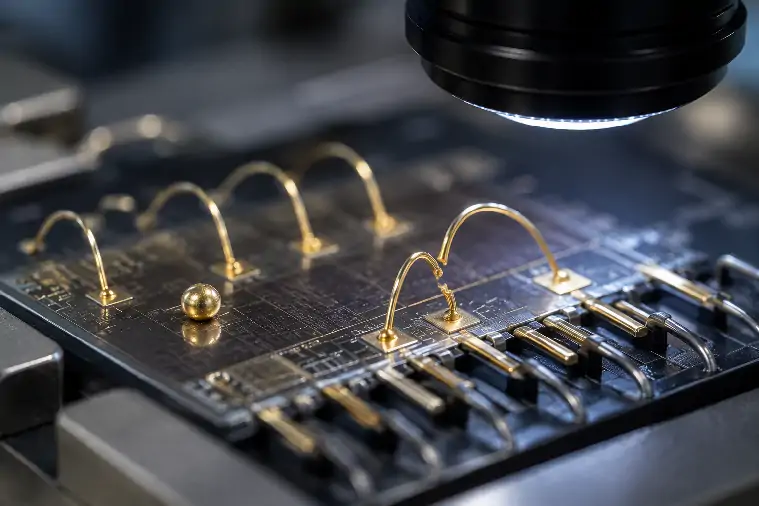
Identify the Defect Before Adjusting the Process
The first troubleshooting question is not “Which parameter should be increased?” It is “What exactly failed, where did it fail and under which conditions did it occur?”
Record the following information before changing the recipe:
Machine model, bond head and software recipe
Wire material, diameter, spool and production lot
Capillary part number, installation time and accumulated bond count
Die pad, leadframe or substrate finish
Package, workholder and heater condition
Defect location within the device or bonding area
Whether the defect is continuous, intermittent or lot-dependent
Visual appearance before and after destructive testing
Recent changes to material, tooling, maintenance or machine setup
A defect that begins immediately after a wire, capillary or material-lot change should be investigated differently from one that develops gradually after many production hours.
Use the Failure Location to Narrow the Search
| Observed Defect | Location or Failure Mode | Areas to Investigate First |
|---|---|---|
| Non-stick on pad | The first bond does not adhere to the die pad | Pad contamination, oxidation, free-air-ball condition, capillary, bond force, ultrasonic transfer, heat and package support |
| Ball lift | The bonded ball separates from the pad during production or testing | Interface quality, pad surface, ball deformation, capillary geometry, process window and pad structure |
| Pad peeling or cratering | The pad or material beneath it is damaged or removed | Excessive mechanical stress, hard wire, capillary geometry, package support, pad construction and underlying die structure |
| Non-stick on lead | The second bond does not adhere to the leadframe or substrate | Surface finish, oxidation, contamination, capillary face, wire gripping, second-bond parameters and heater stability |
| Stitch lift | The second bond separates during pull testing or handling | Second-bond contact area, lead finish, capillary wear, wire condition, ultrasonic transfer and tail sequence |
| Heel crack | The wire cracks near the transition from the bond to the loop | Loop trajectory, capillary motion, bond deformation, wire properties, repeated mechanical stress and package movement |
| Neck break | The wire breaks above the ball bond or heat-affected region | Free-air-ball formation, EFO condition, wire quality, loop motion and neck geometry |
| Short tail or missing ball | The next free-air ball cannot form correctly | Clamp timing, second-bond strength, wire tear, tail length, EFO electrode and wire feed |
| Loop-height variation | Loops differ in height, shape or clearance | Wire tension, clamp response, capillary movement, recipe, wire stiffness, workholder position and machine calibration |
| Bond-position error | The bond is displaced from the intended pad or lead location | Vision recognition, lighting, fiducials, pattern teaching, stage calibration, package movement and workholder repeatability |
This table is a starting point rather than a final diagnosis. Several root causes can produce a similar visible defect, and more than one source of variation may be present at the same time.
First-Bond Defects Begin Before the Ball Reaches the Pad
In ball bonding, the first bond depends on a stable free-air ball, a suitable capillary, a bondable pad surface and controlled transfer of force, ultrasonic energy and heat.
Non-Stick on Pad
Non-stick on pad, commonly shortened to NSOP, means the first bond did not establish sufficient adhesion with the die pad. The failure may be detected immediately by the machine or discovered during inspection and testing.
Possible causes include:
Organic contamination, residues or oxide on the pad surface
An irregular, oxidized or off-center free-air ball
A worn, contaminated or incorrectly selected capillary
Insufficient or unstable ultrasonic energy transfer
Unsuitable force, bonding time or workholder temperature
Poor die support, package movement or workholder instability
Pad metallization that is too thin, damaged or outside its intended condition
A wire material or diameter that does not match the established recipe
Increasing ultrasonic energy may temporarily improve adhesion, but it can also hide contamination or increase pad damage. The surface, free-air ball and tool should be inspected before the process window is widened.
Ball Lift
A ball lift occurs when the first bond separates from the pad during pull testing, downstream handling, molding or reliability testing.
The bond may have appeared acceptable during production while containing limited interfacial contact or an unstable metallurgical connection. Review the underside of the lifted ball, the remaining pad surface and the corresponding test result.
A clean separation at the interface suggests a different problem from a failure that removes pad metal or underlying die material.
Pad Peeling and Cratering
Pad peeling removes part of the pad metallization. Cratering involves damage below the pad and may affect dielectric or silicon structures beneath the bonding area.
These failures should not be treated simply as evidence that the bond is “too strong.” Possible contributing factors include:
Excessive force or ultrasonic interaction
A harder wire material combined with a sensitive pad structure
Unsuitable capillary tip or chamfer geometry
Insufficient support beneath the die or package
Weak pad adhesion or an unsuitable metallization stack
Voids or structural weakness beneath the bonding area
When pad damage appears, repeatedly reducing one parameter without examining the pad construction and package support may not solve the root cause.
Second-Bond Defects Often Reveal Surface and Tooling Problems
The second bond has a smaller and thinner contact area than the first ball bond. Its result depends strongly on the capillary face, wire gripping, terminal surface and tail-formation sequence.
Non-Stick on Lead
Non-stick on lead, or NSOL, occurs when the stitch bond fails to adhere to the leadframe, substrate or package terminal.
Investigate:
Oxidation, plating variation or contamination on the terminal
Capillary face wear or material buildup
Wire gripping and deformation under the capillary
Second-bond force, ultrasonic response and bonding time
Heater temperature and package contact with the workholder
Terminal movement, flexing or inadequate support
Wire, leadframe or substrate lot changes
If defects cluster in one area of a strip or substrate, inspect local flatness, support and temperature distribution rather than changing the entire recipe immediately.
Stitch Lift and Weak Second Bonds
A stitch may remain attached during production but lift during pull testing or subsequent handling. Examine whether the failure occurred at the interface, within the wire or near the heel.
Weak second-bond performance can also affect wire tearing and tail formation. An inconsistent tail can then create an unstable free-air ball for the next wire, causing the original second-bond problem to appear later as a first-bond defect.
This connection is why troubleshooting should follow the complete bonding cycle rather than treating each alarm as an isolated event.
Wire and Loop Defects Point to Motion, Tension and Geometry
Heel Cracks
The heel is the transition between the bonded wire and the rising loop. Cracks in this region may result from excessive deformation, sharp capillary movement, unsuitable loop geometry, repeated package stress or interaction with downstream processes.
Check the crack location and direction under magnification. A crack that appears immediately after bonding may have a different origin from one that develops after molding, thermal cycling or vibration.
Neck Breaks
The neck above a ball bond is influenced by the free-air-ball process and subsequent loop motion. An irregular heat-affected region, poor ball centering or aggressive reverse motion can reduce neck strength.
Review:
Wire and spool condition
EFO electrode position and cleanliness
Free-air-ball size and symmetry
Ball position beneath the capillary
Reverse motion and loop trajectory
Break location during pull testing
Loop Variation and Wire Sweep
Loop variation may involve height, span, shape, direction or clearance. Possible causes extend beyond the programmed loop values.
Inspect the wire tension system, clamp response, capillary movement, wire stiffness, package position and machine calibration. If the loop is stable before molding but moves afterward, the molding process and package design must also be included in the investigation.
Separate Root Causes into Five Groups
A reliable investigation becomes easier when possible causes are grouped before tests are selected.
| Root-Cause Group | Typical Examples | Useful Isolation Method |
|---|---|---|
| Material and surface | Pad contamination, terminal oxidation, plating variation, wire-lot change, molding residue or unstable metallization | Compare known-good material, inspect surfaces, review incoming lots and evaluate cleaning where appropriate. |
| Tooling and consumables | Capillary wear, wrong geometry, contaminated tool face, damaged EFO electrode, unstable wire spool or worn clamp | Install a verified tool or consumable and compare the result under the same process conditions. |
| Process parameters | Unsuitable force, ultrasonic response, time, temperature, EFO, gas, loop or clamp sequence | Return to a known baseline and conduct a controlled process-window study. |
| Machine condition | Transducer degradation, force-calibration drift, heater instability, motion error, vision drift or poor ultrasonic coupling | Use calibration records, diagnostics, known-good material and repeated tests across machine positions. |
| Package and handling | Poor workholder support, die movement, substrate warpage, incorrect indexing, package vibration or downstream mechanical stress | Check support, flatness, clamping, location pattern and the condition before and after later processes. |
A parameter change should be made only after the investigation identifies which group is most likely responsible. Otherwise, one source of variation may be compensated temporarily while the actual defect remains.
A Reliable Wire Bond Troubleshooting Sequence
The following sequence is the core of the diagnosis. It reduces unnecessary recipe changes and helps preserve useful evidence.
Preserve the failed condition. Record the machine, recipe, material lot, tool life, defect image, alarm and affected position before resetting or replacing components.
Classify the failure location. Determine whether the defect is at the first bond, second bond, neck, heel, loop, wire tail, package position or machine-handling stage.
Review the failure mode. Use visual inspection and the applicable pull, shear or electrical result to distinguish interface lift, wire break, pad damage and structural failure.
Check recent changes. Review new wire, capillary, pad, leadframe, substrate, recipe, maintenance work, heater setup, software or operator actions.
Compare with a known-good reference. Run verified material, a verified capillary or a previously stable recipe where this can be done safely. Change one controlled factor at a time.
Separate material from machine. Where possible, test the suspect material on a known-good setup or run known-good material on the suspect machine.
Verify tooling and calibration. Check capillary installation, bond-force calibration, EFO condition, transducer status, workholder support, heater stability and vision alignment.
Develop or restore the process window. Adjust process variables through a controlled study rather than repeated trial-and-error changes to production recipes.
Repeat the complete bonding cycle. Confirm free-air-ball formation, first bond, loop, second bond, tail and the next ball over enough cycles to expose intermittent failures.
Confirm the corrective action with evidence. Compare defect rate, visual result, failure mode and mechanical or electrical test results before releasing the process.
A correction is not confirmed merely because the alarm disappears. The bond result and failure distribution should return to an agreed stable condition.
Use the Right Evidence for the Failure
Visual Inspection
Microscopic inspection can evaluate bond position, deformation, tail length, loop height, heel condition, wire damage and visible contamination. Images should include both acceptable and defective examples under consistent magnification and lighting.
Wire Pull Testing
Wire pull testing can provide information about bond adhesion, heel strength, loop behavior and failure location. Record the force result together with the failure mode because equal force values can represent different weaknesses.
Bond Shear Testing
Shear testing may be appropriate for applicable ball bonds, bumps, heavy-wire bonds or other structures. The test method, tool height, direction and acceptance criteria must match the interconnect being evaluated.
Cross-Section and Pad Analysis
Cross-sectioning or further material analysis may be required when pad peeling, cratering, subsurface cracking, limited interfacial formation or package-structure damage is suspected.
Machine Process Monitoring
Some wire bonders monitor force, ultrasonic response, wire deformation, frequency behavior or individual bonding substeps. These signals can identify changes and support traceability, but their limits must be established for the product and verified against physical bond results.
Electrical and Reliability Testing
Electrical testing and package-level reliability tests become important when mechanical bonding results appear acceptable but field conditions, current, moisture, temperature or repeated stress may expose another failure mechanism.
Surface Cleaning Should Follow Evidence
Surface contamination and oxidation can contribute to NSOP and NSOL. Cleaning may improve bondability when the contaminant and selected cleaning method are understood.
Do not assume that every weak bond requires plasma cleaning. Before adding a cleaning step, determine:
Which surface is contaminated or oxidized
Whether the material can tolerate the proposed treatment
Whether cleaning changes the surface finish or package condition
How quickly the cleaned material must be bonded
How the result will be verified against an untreated baseline
Available surface-preparation systems can be reviewed through the Semimachine plasma cleaner category. Process compatibility must still be confirmed for the actual die, leadframe, substrate and contaminant.
Capillary and Replacement Parts Affect More Than Downtime
Capillary geometry influences ball formation, bonded-ball diameter, pad interaction, looping, wire gripping and second-bond stability. Wear or contamination can therefore create several defects at once.
When reviewing a suspected capillary problem, record:
Full capillary part number and drawing revision
Wire material and diameter
Accumulated bonds or operating time
Tip, chamfer, hole and face condition
Material buildup or visible damage
Defect rate before and after replacement
Wire clamps, EFO electrodes, transducers, heaters, cameras, lighting, workholders and handling components can also change process stability. The wire bonder parts and capillary category provides an entry point for identifying applicable tooling and replacement components.
Conditions That Require Production to Stop
Stop the process and preserve evidence when:
Pad peeling, cratering or die damage is detected
The same bond lift or non-stick defect repeats after a controlled reset
Wire breaks create a risk of loose conductive material
The capillary, transducer, clamp or EFO component is visibly damaged
Force, heater, ultrasonic or vision calibration is outside its accepted condition
The defect rate changes sharply after a material or tooling lot change
A machine alarm is repeatedly bypassed without identifying its cause
The process passes visual inspection but fails the required mechanical or electrical test
Continuing production while repeatedly increasing process energy may convert a recoverable bonding problem into pad damage, tool wear or a larger reliability risk.
Wire Bonding Defects FAQ
What is the first step when NSOP suddenly increases?
Preserve the failed samples and record recent changes. Inspect the pad surface, free-air ball, capillary and affected positions before changing the complete bonding recipe.
Does a high pull value prove that the wire bond is good?
Not by itself. The failure location and mode are also important. A high result accompanied by pad peeling, cratering or another structural failure may indicate an unacceptable process.
Should ultrasonic power be increased when a bond does not stick?
Not automatically. Poor adhesion may come from contamination, oxidation, capillary wear, unstable ball formation, weak support or equipment condition. Increasing power without isolating the cause may damage the pad.
Can a new capillary solve both first- and second-bond defects?
It may solve defects caused by wear, contamination or unsuitable geometry, but it will not correct every material, package, calibration or process problem. Compare the result with a verified capillary under controlled conditions.
Why does the defect occur only in one area of the package?
A location-specific pattern may indicate workholder support, temperature distribution, package warpage, vision alignment, local surface condition or motion-related variation. Map the defect position before changing global parameters.
Final Recommendation
Wire bond troubleshooting should begin with evidence, not parameter guessing. Identify the failure location, preserve the failed condition, distinguish material and tooling problems from machine and process problems, and change one controlled factor at a time.
Use visual inspection, failure-mode analysis, pull or shear testing and machine diagnostics together. A corrective action is complete only when the intended bond result remains stable across repeated cycles and representative production conditions.
Available wire bonder equipment, tooling and replacement components can be reviewed against the affected process. To discuss a machine fault or recurring bond defect, send the bonder model, defect photographs, wire and capillary information, alarm details and recent process changes through the Semimachine contact page.