The ACCRETECH FP2000 is an automatic frame-handling wafer prober developed for electrical testing of diced wafers, semiconductor packages and compatible devices attached to dicing frames. It can also handle compatible 5- to 8-inch wafers, allowing framed products and standard wafers to be tested on the same prober configuration.
The actual loader, frame-handling parts, chuck, test-head interface, probe-card setup and optional inspection functions depend on the specific pre-owned machine available. For an initial inquiry, send your current prober or tester model, clear photos of the wafer or frame and a short description of the required test process or equipment problem.
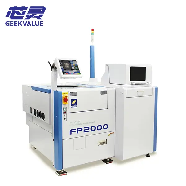
ACCRETECH FP2000 Machine Information
| Manufacturer | ACCRETECH / Tokyo Seimitsu |
|---|---|
| Model | FP2000 |
| Equipment Type | Automatic frame-handling wafer prober |
| Primary Application | Electrical testing of diced wafers, packages and compatible devices attached to dicing frames |
| Frame Capability | 200 mm framed wafer handling according to the manufacturer’s model information |
| Wafer Capability | Compatible 5- to 8-inch wafers |
| Typical Products | CSP, WLCSP, diced wafer, package and compatible MEMS applications |
| Primary Functions | Frame or wafer loading, alignment, position correction and probe-card contact |
| Condition | Pre-owned semiconductor test equipment |
| Test Configuration | Determined by the tester, test head, probe card, chuck and installed interfaces |
| Delivery Scope | Based on the quotation and confirmed equipment list |
| Support | Initial fault review, parts matching and repair discussion |
| Shipping | Export packing and worldwide delivery |
Frame, Wafer and Device Compatibility
The FP2000 model name and 200 mm frame capability do not by themselves confirm compatibility with a particular product. The available machine must also match the dicing frame, wafer size, die layout, package condition, probe card, tester, chuck and required contact method.
Only basic information is needed for the first discussion:
- Your current wafer prober or tester model if the FP2000 will replace existing equipment
- Clear photos of the dicing frame, wafer, package or device to be tested
- The probe-card or test-head model where this information is readily available
- A short description of the required test process or current equipment problem
Detailed frame dimensions, wafer maps, die pitch, interface drawings and test conditions can be reviewed later when the available machine appears relevant to the project.
Testing Diced Wafers and Framed Devices
The FP2000 is intended to transfer and test products that remain attached to a dicing frame after wafer cutting. Its correction software helps compensate for positional differences across the framed product so that individual dies or packages can be aligned with the probe card.
This makes the machine relevant to applications where die position may vary after dicing or where CSP, WLCSP, MEMS or other framed products need to be electrically tested before the next packaging step. Reliable results still depend on stable frame loading, correct alignment, suitable correction settings and consistent probe-card contact.
Tester, Probe Card and Frame Integration
The FP2000 handles the frame or wafer and positions the device beneath the probe card, while electrical measurements are performed by the connected tester. The prober, probe card, test head, manipulator, tester and software communication must therefore be checked as one complete test cell.
An existing probe card, test head or frame should not be assumed to fit the available machine based only on the brand or wafer size. The mounting arrangement, frame format, chuck setup, contact position and tester interface must be reviewed before installation.
Available FP2000 Configuration and Delivery Scope
Individual ACCRETECH FP2000 wafer probers may differ in frame loaders, wafer-handling components, chuck configuration, test-head manipulator, barcode functions, high-temperature equipment, probe-mark inspection and software options. Before purchase, the available machine should be reviewed to confirm whether its actual frame-handling and test configuration is suitable for the intended product and tester. The final delivery scope is based only on the quotation and confirmed equipment list; testers, test heads, manipulators, probe cards, frames, cassettes, chillers, computers and interface components are included only when specifically stated.
Receiving, Startup and Initial Frame Test
The FP2000 should be inspected and tested in stages before valuable production wafers or framed devices are introduced.
- Inspect the packing, machine cabinet, frame loader, wafer stage, chuck, control panel and visible handling mechanisms.
- Photograph any impact marks, loose components, damaged cables or displaced assemblies before moving the equipment.
- Compare the received machine, loader parts, manipulator, interfaces and accessories with the confirmed delivery list.
- Check that the chuck, stage, alignment system and frame-handling components remain secured after transportation.
- Confirm the electrical supply, grounding, compressed air, vacuum, cooling and other facility requirements of the actual machine.
- Start the controller and record all alarm messages before resetting the system or changing settings.
- Run the loader, alignment and stage mechanisms without a production frame and observe their movement.
- After basic operation is stable, use a suitable non-production frame or wafer for loading, correction, stepping and unloading checks.
The probe card, test head and tester should then be connected and verified separately before electrical results are evaluated. Stop testing if the frame shifts, handling is unstable, stage movement is abnormal, mechanical interference occurs or the same alarm repeatedly returns.
Alignment, Contact and Parts Support
Unstable test results may involve frame deformation, die-position variation, incorrect correction data, wafer alignment, probe-card condition, chuck setup, test-head connection or tester communication.
Frame-loading faults, barcode errors, alignment failures, inconsistent probe marks and contact-position differences should be investigated before production continues. Record the alarm message and the stage of the test cycle in which the problem occurs before resetting the machine.
Photos of the frame, wafer, probe card, chuck, test-head connection and alarm screen, together with a short operating video where available, can provide a practical starting point for review.
Our team can assist with initial fault analysis, component identification, replacement-part matching and repair discussion. Related sensors, motors, drivers, boards, cables, vacuum components, loader assemblies, stage parts and chuck-related components can also be checked where available.
Frequently Asked Questions
Can the ACCRETECH FP2000 test our diced wafer or package?
This depends on the frame format, wafer or package layout, probe card, tester, chuck configuration and required contact conditions. Send frame and product photos for an initial review.
Can the FP2000 test both framed products and standard wafers?
The model platform supports frame handling as well as compatible 5- to 8-inch wafer handling. The loaders and handling parts installed on the available machine must still be confirmed.
Does the FP2000 support 6-inch frames?
Support for 6-inch frames was offered as an option. The required loader and frame-handling configuration should be confirmed on the specific machine.
Is the tester or probe card included?
Only testers, test heads, manipulators, probe cards and interface components specifically listed in the quotation or confirmed delivery scope are included.
Can you assist with frame loading, alignment or contact problems?
Yes. Send the machine model, alarm information, frame and probe-card photos and an operating video where available. We can assist with initial fault review, parts matching and repair discussion.
Contact Us About the ACCRETECH FP2000
Send your current wafer prober or tester model, frame, wafer or device photos and a short description of the test requirement or equipment problem. We will review the basic application first and continue with the necessary probe-card, test-head interface, frame-handling configuration, replacement-parts or repair details afterward.