Die bonding is often described as a simple pick-and-place operation: a die is removed from a wafer and attached to a leadframe, substrate or carrier. In production, however, accurate placement is only one part of the result.
The die bonding process must also control how the die is picked up, how the bonding material is applied, how the die and substrate are aligned, how force and height are managed, and how the assembly behaves during curing, soldering or another downstream bonding step.
This is why two die bonding machines with similar placement specifications may produce very different results on the same package. Their vision systems, ejectors, bond heads, dispensers, heaters, tooling and material-handling configurations may not be equivalent.
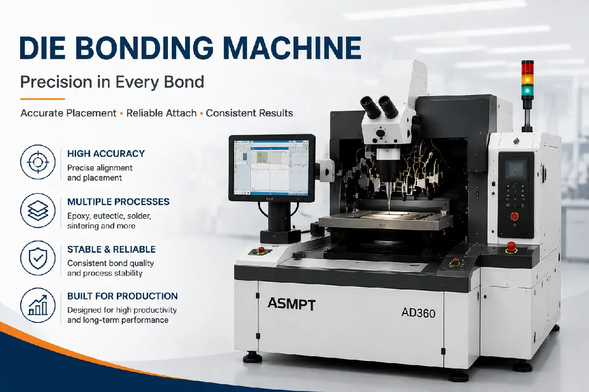
What a Die Bonding Machine Actually Controls
A die bonder connects several individual operations into one repeatable assembly sequence. The exact sequence varies by product and bonding material, but most die bonding processes include five functional stages:
Presenting and identifying the die
Picking the die without damaging or contaminating it
Preparing the bonding material and substrate
Aligning and placing the die under controlled conditions
Inspecting the result and transferring the assembly downstream
The machine does not independently guarantee a reliable die attach joint. It creates and controls the conditions required by the selected material and package design.
For epoxy die attach, the final joint may not be established until the adhesive is cured. For eutectic or solder bonding, the result also depends on temperature, atmosphere, surface condition and wetting. In silver sintering, the die bonder may perform material application, placement and tacking while final densification occurs in another process.
The Die Bonding Process from Wafer to Substrate
1. Die Presentation and Wafer Mapping
The process begins with a known die source. Dies may be supplied on a diced wafer frame, in a waffle pack, Gel-Pak, tray, feeder or another carrier.
When dies are picked directly from a wafer, the machine may need to coordinate:
Wafer identification and orientation
Wafer-map or known-good-die information
Die position and street recognition
Frame movement and expansion condition
Ejector position and pickup timing
Bad-mark or rejected-die handling
A machine that supports the correct wafer diameter may still be unsuitable when its frame type, ejector arrangement, wafer-map format or die-pick method does not match the product.
2. Die Ejection and Pickup
The die must be separated from the tape and transferred to the bond head without cracking, chipping, rotating or contaminating it.
This stage becomes more difficult when the process uses:
Very small dies
Thin or warped dies
Brittle compound-semiconductor materials
Large dies with significant surface area
Dies with sensitive top-side structures
Backside coatings or metallization that can be scratched
The ejector needle, support geometry, tape condition, pickup tool, vacuum level and motion profile work together. Increasing ejector travel or vacuum without understanding the failure mechanism can transfer the problem from incomplete pickup to die cracking or surface damage.
3. Bonding Material Preparation
The machine may need to dispense, stamp, dip or otherwise present the die attach material before placement.
| Material Route | Typical Machine Function | Main Process Concern |
|---|---|---|
| Conductive or non-conductive epoxy | Dispensing, jetting, stamping or dipping | Deposit volume, pattern, bleed, open time and cure behavior |
| Eutectic alloy or preform | Preform handling, heating, atmosphere control and optional scrub | Wetting, oxidation, temperature uniformity and die movement |
| Soft solder | Solder preparation, heated process zone and controlled transport | Bond-line thickness, wetting, voiding and production repeatability |
| Silver sintering material | Paste dispensing, film handling, placement and tacking | Material uniformity, bond-line control and transfer to final sintering |
| UV-curable adhesive | Dispensing, alignment, placement and UV exposure | Working time, shadow areas, cure dose and component stability |
The material name alone is not enough to define the equipment. Viscosity, filler content, deposit size, pot life, storage condition and required pattern can change the suitable dispensing technology.
4. Vision Alignment
The vision system identifies reference features on the die and the destination surface. The machine then calculates the required X, Y and rotational correction before placement.
Reliable alignment depends on more than camera resolution. The system must also manage:
Reflective, transparent or low-contrast surfaces
Changing die orientation
Substrate fiducials and package references
Tool-center and camera calibration
Height differences between products
Thermal expansion during heated bonding
Post-bond movement caused by the material
A vision system may locate the die accurately before placement while the final position still shifts during compression, curing or solder reflow. Pre-bond alignment and final post-bond accuracy should therefore be treated as related but different measurements.
5. Controlled Placement and Bonding
During placement, the bond head moves the die toward the substrate and establishes the required position, height and force.
Depending on the process, the machine may control:
Approach speed
Contact detection
Bond height or final Z position
Placement force
Dwell time
Bond-head and stage temperature
Scrub or programmed die movement
Inert or reducing atmosphere
Cooling before release
These controls should not be considered independent. Force can change bond-line thickness. Temperature can change material viscosity and wetting. Scrub can influence voiding and final alignment. Tool parallelism can cause one side of the die to contact before the other.
6. Post-Bond Inspection and Transfer
After placement, the machine may inspect die presence, position, rotation, surface condition or adhesive spread. More advanced systems may also measure height, parallelism or post-bond offset.
Inspection must match the defect that needs to be controlled. A top-view camera may detect missing or rotated dies, but it cannot directly prove internal void level, complete adhesive coverage or final joint reliability.
The assembly may then proceed to curing, reflow, sintering, wire bonding, molding or another package-specific operation.
Placement Accuracy Is Not One Universal Number
Placement accuracy is one of the most visible die bonding machine specifications, but it is also one of the easiest to compare incorrectly.
A published accuracy value may depend on:
The statistical definition, such as one sigma or three sigma
The die dimensions and surface features
The machine speed used during testing
The selected camera and field of view
The bond head and pickup tool
The substrate size and working area
Whether the measurement is made before or after bonding
The process temperature and material behavior
For this reason, a lower numerical specification does not automatically mean better production performance. The specification must be read together with the real package tolerance and process conditions.
| Accuracy Requirement | Typical Process Priority | Equipment Direction |
|---|---|---|
| Standard package placement | Stable high-volume die attach and predictable material flow | Production-focused automatic epoxy die bonder |
| Precision sensor or optoelectronic placement | Tighter alignment, controlled force and stable post-bond position | High-precision die bonding platform |
| Fine-pitch face-down interconnection | Alignment between die interconnects and substrate pads | Flip chip or thermocompression-capable system |
| Optical or photonic assembly | Relationship between electrical placement and optical alignment | Ultra-precision die bonder with specialized vision and metrology |
The ASMPT AD280 Plus, for example, represents a precision-oriented equipment direction, while the ASM AD830 Plus represents an automatic production platform. Their suitability should be judged by the application and installed configuration rather than by one headline number.
Bond-Line Thickness Connects the Machine to the Final Joint
Bond-line thickness is the distance between the die backside and the bonding surface after placement and material compression.
It can affect:
Thermal resistance
Electrical behavior
Mechanical stress
Die tilt
Adhesive bleed
Void formation
Package height
Long-term reliability
The die bonder influences bond-line thickness through deposit volume, bond height, force, tool parallelism and placement repeatability. The final value can also change during curing, reflow or sintering.
This means bond-line control should not be reduced to a single force setting. The process needs a stable relationship among:
Material volume
Material rheology or melting behavior
Die and substrate flatness
Tool parallelism
Programmed height and force
Thermal or curing profile
When the bond line is inconsistent, changing machine force may hide the symptom without correcting an unstable deposit, warped substrate or unsuitable tooling.
Bond Force Must Match the Die and Material
Bond force helps establish contact, spread material, seat a preform or support a pressure-assisted process. More force is not automatically better.
Excessive or poorly controlled force may contribute to:
Die cracking
Substrate damage
Excessive adhesive squeeze-out
Uncontrolled bond-line reduction
Die movement
Damage to bumps or delicate structures
Insufficient force may result in incomplete contact, unstable tacking, excessive bond-line thickness or poor material spreading.
The relevant specification is not only the machine’s maximum force. The process may also depend on low-force resolution, closed-loop control, contact detection, force stability and tool compliance.
Temperature and Atmosphere Change the Meaning of Placement
In room-temperature epoxy placement, the die may remain movable until the material begins to cure. In eutectic and solder processes, the die may be positioned while the bonding layer is heated or molten. In sintering, placement and tacking may be followed by a separate high-temperature and pressure step.
Heating changes:
Material viscosity
Wetting behavior
Oxidation risk
Die and substrate dimensions
Tool expansion
Adhesive working time
Final bond-line formation
A suitable die bonding machine may therefore require heated tools, a heated stage, localized heating, atmosphere control, temperature monitoring or controlled cooling.
The ASMPT AD211 Plus eutectic die bonder illustrates a specialized thermal bonding direction. It should not be evaluated in the same way as a standard room-temperature epoxy placement machine.
Throughput Must Include the Complete Process
Units per hour can help estimate production capacity, but maximum placement speed rarely represents the complete factory cycle.
Actual output may include time for:
Wafer and substrate loading
Bad-die recognition
Tool or ejector changes
Material dispensing or stamping
Vision alignment
Heating and cooling
Bond-force dwell
Post-bond inspection
Magazine changes
Recipe changeover
A machine with a high nominal UPH may produce less usable output when the application requires long alignment, multiple materials, frequent tool changes or extensive inspection.
Conversely, a slower precision platform may be the better production choice when a placement error would make the completed optical or semiconductor assembly unusable.
How Common Die Bonding Problems Relate to the Process
A defect should be treated as evidence that narrows the investigation, not as proof of one root cause.
| Observed Result | Process Areas to Investigate |
|---|---|
| Die shifted or rotated | Vision reference, pickup orientation, tool release, material movement, scrub, reflow or fixture stability |
| Die tilt or uneven height | Deposit uniformity, tool parallelism, substrate flatness, contamination, bond-height control or force distribution |
| Excessive epoxy bleed | Deposit volume, viscosity, temperature, force, placement height, die size or cure delay |
| Incomplete adhesive coverage | Deposit pattern, material condition, surface energy, placement force, bond line or trapped contamination |
| Die crack or chip | Ejector setup, pickup tool, tape release, force, support, motion profile or die thickness |
| High void level | Material preparation, dispense pattern, surface condition, atmosphere, scrub, reflow, cure or downstream vacuum process |
| Unstable placement accuracy | Calibration, vision contrast, tool centering, stage condition, thermal drift, vibration or product presentation |
The first diagnostic question should be where the variation enters the sequence. Compare a known-good cycle with the failing cycle and isolate wafer handling, pickup, material application, alignment, placement and downstream bonding one stage at a time.
How to Read Die Bonding Machine Specifications
Before comparing machine models, translate each specification into a product requirement.
| Machine Specification | Question It Should Answer |
|---|---|
| X/Y and theta accuracy | Can the machine place the die within the package tolerance under the intended process conditions? |
| Die-size and thickness range | Can the pickup, ejector and tooling handle the actual die without damage? |
| Wafer and tray support | Can the machine accept the production material format and mapping method? |
| Bond-force range | Does the machine provide the required force with suitable resolution and control? |
| Heating capability | Can the bond head, stage and atmosphere support the bonding material and thermal profile? |
| Dispensing options | Can the installed system handle the material, viscosity, deposit pattern and required volume? |
| UPH or cycle time | What output remains after material application, alignment, heating and inspection are included? |
| Post-bond inspection | Which placement or process defects can the machine detect before the product moves downstream? |
The machine specification sheet defines a possible operating envelope. Representative material testing is still needed to determine whether the exact die, substrate, adhesive, solder or sintering route can run reliably.
A Practical Process-to-Machine Review
A die bonding machine should be reviewed in the same order as the real assembly process.
Define the final joint. Record its mechanical, thermal, electrical and reliability requirements.
Confirm the die. Document dimensions, thickness, material, backside condition and input format.
Confirm the substrate. Record dimensions, finish, flatness, fiducials and handling method.
Define the bonding material. Include application method, storage, temperature and downstream cure or reflow.
Set the placement tolerance. Separate pre-bond alignment from final post-bond position.
Define height and force. Connect them to bond-line and package requirements.
Review thermal needs. Identify tool heating, stage heating, atmosphere and cooling requirements.
Calculate realistic output. Include all handling, alignment, bonding and inspection steps.
Check the installed configuration. Verify heads, cameras, loaders, dispensers, heaters, software and tooling.
Test representative material. Evaluate the complete process rather than a dry machine cycle alone.
This sequence prevents a common mistake: selecting a die bonder because its maximum accuracy or throughput looks suitable, then discovering that the installed material-handling or bonding modules cannot reproduce the required process.
Die Bonding Process FAQ
Is die bonding the same as die attach?
The terms are frequently used for the process of placing and attaching a semiconductor die to a leadframe, substrate, carrier or another component. The exact bonding mechanism may use epoxy, solder, a eutectic alloy, sintering material or another process.
Does a die bonding machine complete the final joint?
Not in every process. Some machines complete heating or eutectic bonding in place. In other applications, the die bonder performs material application, placement or tacking before the assembly moves to curing, reflow or sintering equipment.
What is the most important die bonder specification?
There is no single most important number. Placement accuracy, die handling, material application, bond force, heating, vision, throughput and inspection must all match the product and bonding process.
Why can the die move after accurate vision alignment?
The die may shift during tool release, material compression, scrub, curing, solder melting or thermal movement. This is why post-bond position can differ from the alignment result measured before placement.
How should a die bonding machine be tested before selection?
Use representative die, substrate, material and tooling whenever practical. Confirm pickup, material application, alignment, placement, bond-line behavior, inspection and downstream process compatibility under agreed conditions.
Final Perspective
Die bonding quality is created by a controlled sequence, not by placement accuracy alone. Wafer presentation, die pickup, material application, alignment, bond height, force, temperature and inspection all contribute to the final result.
The right machine is the one whose installed configuration can reproduce that complete sequence with acceptable stability and output.
Review available die bonding machines and die attach systems, then provide the die, substrate, bonding material, accuracy target, throughput and required process modules through the GEEKVALUE semiconductor equipment inquiry page for a configuration-based review.