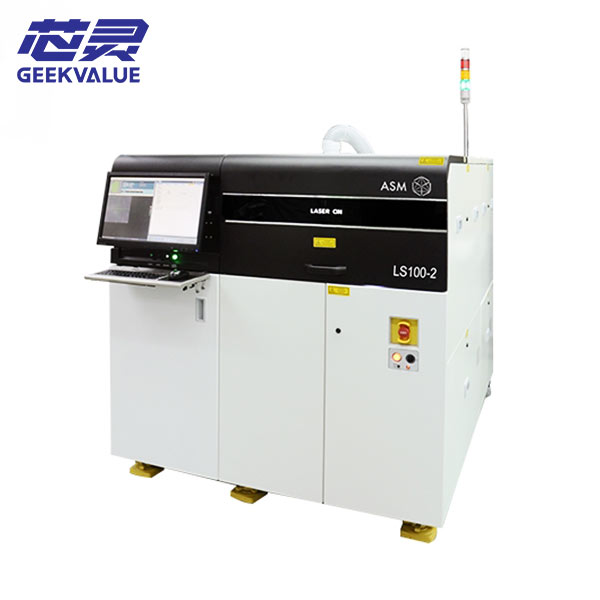
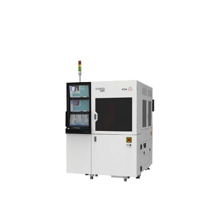
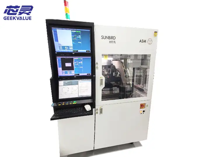
The ASM AD830 Plus, identified as AD830PLUS in the machine documentation, is a fully automatic high-speed silver-epoxy die bonder designed for wafer-to-lead-frame semiconductor die attach. Its production sequence integrates lead-frame loading, silver-epoxy application, die pickup from a wafer, precision die placement, visual inspection and automatic unloading.
Also searched as the ASM AD 830 PLUS, ASMPT AD830Plus or AD 830 Plus die bonder, this machine is suitable for production environments that require automated material handling, programmable bonding parameters, wafer alignment and in-process quality inspection.
We support customers evaluating an ASM AD830 Plus for semiconductor production expansion, replacement of an existing die bonder or second-hand equipment sourcing. Depending on machine availability and project requirements, support may include configuration review, condition inspection, functional testing, tooling confirmation, packaging, international shipment and technical assistance.
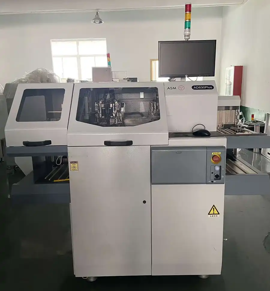
ASM AD830 Plus Machine Overview
| Manufacturer | ASM / ASM Pacific Technology |
|---|---|
| Model | AD830 Plus / AD830PLUS |
| Equipment Type | Fully Automatic High-Speed Die Bonder |
| Primary Process | Silver-epoxy wafer-to-lead-frame die attach |
| Nominal Cycle Time | 163 ms under specified machine and process conditions |
| Bond Head | Single X-Y-Z linear-motion bond head with voice-coil bond arm |
| Die Size Range | 6 x 6 to 200 x 200 mil, approximately 150 x 150 to 5,080 x 5,080 µm |
| Maximum Wafer Size | Up to 8 inches |
| Lead-Frame Length | 110 to 300 mm; optional configuration for 80 to 110 mm |
| Lead-Frame Width | 12 to 102 mm |
| Lead-Frame Thickness | 0.12 to 0.76 mm |
| Pick and Bond Force | 30 to 300 g; optional configuration from 300 g to 3 kg |
| Epoxy Process | Optional silver-epoxy dispensing or stamping configuration |
| Vision Resolution | 480 x 480 pixels with 256-level grayscale PR imaging |
| Inspection Capability | Work-holder PR, wafer PR, die PR, pre-bond inspection and post-bond inspection |
| Wafer Theta Correction | ±10° correction range with 0.001875° per step |
| Power Supply | 110-240 VAC, single phase, 50/60 Hz |
| Compressed Air | Minimum 6 bar / 87 PSI |
| Power Consumption | 1,250 W |
| Machine Availability | Subject to current inventory, installed configuration and equipment condition |
Machine specifications and production capability must be confirmed against the actual nameplate, installed modules, software, tooling, package design and process materials.
What Is the ASM AD830 Plus Die Bonder?
The ASM AD830 Plus is an automatic die bonding system that picks individual semiconductor dies from a wafer and attaches them to prepared positions on a lead frame. Before die placement, the machine can apply silver epoxy through a configured dispensing or stamping process.
A typical AD830 Plus production sequence begins when the machine receives a lead-frame magazine or stacked lead-frame supply. An individual lead frame is transferred to the work-holder track, positioned at the epoxy-processing station and then moved to the die bonding position.
At the wafer table, the ejector mechanism separates the selected die from the adhesive film. The collet applies vacuum, picks the die and transfers it to the bonding position. The die is then placed onto the silver epoxy according to the programmed coordinates, height, force and orientation.
The completed lead frame continues through the transport system and is loaded into an output magazine. This integrated process reduces manual handling between lead-frame loading, epoxy application, die placement and inspection.
Key Features of the ASM AD830 Plus
Fully automatic wafer-to-lead-frame die bonding process
Nominal cycle time of 163 ms under specified operating conditions
Single X-Y-Z linear-motion bond head
Linear-motor and linear-encoder motion control
Voice-coil bond arm for controlled pick and bond movement
Programmable pick force and bond force
Airflow-based missing-die detection
Automatic die re-pick capability after a missing-die condition
Automatic wafer-table theta calibration
Lead-frame position detection and process-position compensation
Optional silver-epoxy dispensing or stamping assemblies
Pre-bond and post-bond inspection capability
480 x 480 pixel pattern-recognition system
Programmable LED-array illumination for optical inspection
Multi-magazine output handling
Optional automatic wafer loading and unloading
Package-file storage for product and process settings
Automatic Wafer-to-Lead-Frame Die Attach
The documented operating process of the AD830 Plus is based on transferring dies from a wafer to a lead frame. The machine coordinates several modules to complete the production cycle automatically.
Lead-frame loading: Lead frames are supplied from an input magazine or optional stack-loading system.
Lead-frame transfer: The work-holder transports the lead frame along the processing track.
Epoxy application: Silver epoxy is applied through dispensing or stamping, depending on the installed module.
Wafer positioning: The wafer table moves the selected die to the pickup position.
Die recognition: The pattern-recognition system identifies the die and calculates the required correction.
Die separation: The ejector pin lifts the die from the adhesive film.
Die pickup: The collet applies vacuum and picks the separated die.
Die transfer: The X-Y-Z bond-head assembly moves between the wafer and bonding positions.
Die placement: The die is placed onto the prepared silver-epoxy position using programmed height and force.
Post-bond inspection: The optical system checks the completed placement according to the production recipe.
Output handling: Completed lead frames are transferred to the output magazine.
The exact sequence may vary according to the installed input system, wafer loader, epoxy module, inspection options and customer package design.
High-Speed Die Bonding Performance
The ASM AD830 Plus manual specifies a nominal cycle time of 163 milliseconds. This figure represents the machine cycle under defined operating and process conditions and should not be interpreted as a guaranteed production output for every package.
Actual production performance is affected by several factors:
Die dimensions and thickness
Wafer condition and die spacing
Lead-frame dimensions and bond-pad layout
Number of bonding positions per lead frame
Epoxy dispensing or stamping parameters
Required pick and bond force
Vision-search and inspection settings
Wafer-map processing
Lead-frame loading and unloading time
Machine condition and calibration status
Frequency of package changeovers
Before purchasing a machine for a specific production target, representative dies, wafers, lead frames and process information should be reviewed. A sample production test provides a more reliable evaluation than a dry-cycle demonstration alone.
Single X-Y-Z Linear-Motion Bond Head
The AD830 Plus uses a single bond-head assembly with X, Y and Z linear movement. Linear motors and linear encoders control the three-axis motion required for die pickup, transfer and placement.
The bond-head assembly also incorporates a voice-coil bond arm. Together, these components support controlled pickup and bonding movement while maintaining the speed required for automatic production.
The machine allows programmable pick and bond force. The documented standard force range is 30 to 300 grams, while an optional configuration supports a range from 300 grams to 3 kilograms.
When evaluating a second-hand ASM AD830 Plus, the bond-head assembly should be inspected for:
Smooth and repeatable X-Y-Z movement
Abnormal noise or vibration
Linear-motor and encoder alarms
Condition of cables and vacuum tubing
Bond-arm movement and height repeatability
Signs of previous tool or stage collision
Pickup and bonding force stability
Missing-die detection performance
Collet and Ejector System
The collet and ejector system work together to separate and pick individual dies from the wafer. The ejector pin rises beneath the selected die while the collet applies vacuum from above.
Correct setup is important because the die must be separated from the adhesive film without cracking, chipping or shifting. The pickup process depends on the die dimensions, thickness, adhesive-film condition, ejector-pin design, collet design, vacuum level and programmed pickup height.
Tooling that may require inspection or replacement includes:
Collet body and adapter
Die collet
Ejector pin
Ejector-pin holder
Ejector cap
Wafer support and expansion components
Vacuum tubing and fittings
A worn or incorrectly matched collet may cause missing dies, unstable pickup, die damage or placement variation. An unsuitable ejector-pin configuration may also damage the die or prevent reliable separation from the film.
Missing-Die Detection and Automatic Re-Pick
The standard AD830 Plus configuration includes airflow-based missing-die detection. This function helps the machine determine whether a die has been successfully picked by the collet.
When the expected airflow or vacuum condition is not detected, the machine can initiate a re-pick sequence according to the configured process settings. This helps reduce empty placements caused by unsuccessful die pickup.
Missing-die alarms should not automatically be treated as a sensor problem. Possible causes include:
Worn or contaminated collet
Incorrect pickup height
Insufficient or unstable vacuum
Damaged ejector pin
Incorrect ejector height
Poor wafer expansion
Die adhesion to the film
Blocked vacuum tubing
Air leakage
Incorrect airflow-detection settings
Automatic Wafer Table and Theta Calibration
The wafer-table assembly includes an X-Y motion system and an automatic wafer-expansion or wafer-ring structure. The X-Y stage positions each selected die beneath the pickup tool.
An automatic theta-calibration system corrects wafer rotation. The documented theta range is ±10 degrees with an angular step of 0.001875 degrees.
This correction helps the machine maintain the required die orientation during wafer processing. The wafer PR system is used to identify die position and support automatic search and alignment.
Depending on the installed options, the AD830 Plus may also include:
Automatic wafer loading and unloading
Wafer magazine handling
Wafer mapping
Barcode-reading functions
Wafer expansion equipment
These functions are configuration-dependent and should be verified on the actual machine.
Optional Silver-Epoxy Dispensing or Stamping
The ASM AD830 Plus can be configured with silver-epoxy dispensing or stamping assemblies. These modules apply bonding material to the lead frame before die placement.
The documented dual-epoxy structure includes a motor-controlled X stage together with left and right Y stages. Programmable parameters are used to control the epoxy process and the amount of material applied.
Silver-Epoxy Dispensing
In a dispensing configuration, a syringe and dispensing needle deposit controlled epoxy dots onto the selected lead-frame positions. Process parameters may include dispensing height, pressure, delay, position and deposit sequence.
Silver-Epoxy Stamping
In a stamping configuration, a tool transfers silver epoxy from an epoxy tray to the lead-frame bonding position. The process requires the correct stamping tool, epoxy level, anvil and programmed movement.
When inspecting an available machine, customers should confirm whether the supply includes:
Left and right epoxy modules
Dispensing syringes
Dispensing needles
Stamping or dipping tools
Epoxy trays
Epoxy-process optics
Pressure-control components
Required cables, motors and sensors
Corresponding software functions
The epoxy process should be tested using material with characteristics close to the customer's actual silver epoxy. Viscosity, working life, temperature and environmental conditions can affect deposit consistency.
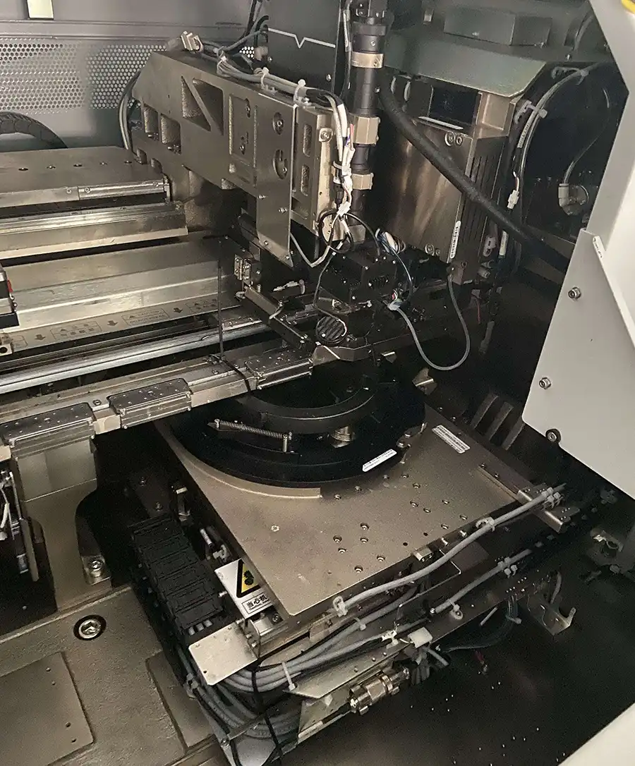
Pattern Recognition and Optical Inspection
The AD830 Plus uses multiple optical functions to support material positioning, die recognition, epoxy alignment and bond inspection. The documented pattern-recognition system provides a resolution of 480 x 480 pixels and uses programmable LED-array illumination.
Optical functions may include:
Work-holder and lead-frame PR
Wafer PR
Die recognition
Left epoxy-process optics
Right epoxy-process optics
Bond-position optics
Pre-bond inspection
Post-bond inspection
Lead-Frame Position Recognition
The work-holder PR system recognizes reference features on the lead frame. Position information can be used to compensate for lead-frame variation before epoxy application and die placement.
Wafer and Die Recognition
The wafer PR system identifies individual dies and supports automatic die searching. The system works together with the wafer table to position the selected die beneath the collet.
Pre-Bond Inspection
Pre-bond inspection can be configured to check the target position before die placement. Depending on the recipe, the machine may evaluate the lead-frame position, epoxy deposit or other visible process conditions.
Post-Bond Inspection
Post-bond inspection checks the result after the die has been placed. Recipe settings may be used to identify missing dies, placement offset, abnormal die rotation, epoxy coverage or epoxy bridging.
The exact inspection capability depends on the installed cameras, lenses, lighting, software version and package recipe. Vision performance should therefore be tested with representative production samples.
Lead-Frame Material Handling
The ASM AD830 Plus is designed to transport lead frames through epoxy application and die bonding stations. The work-holder structure uses parallel tracks and multiple transport components to move the lead frame from the input side to the output side.
The documented lead-frame handling range includes:
Lead-frame length from 110 to 300 mm
Optional short lead-frame configuration from 80 to 110 mm
Lead-frame width from 12 to 102 mm
Lead-frame thickness from 0.12 to 0.76 mm
Track-width range from 12 to 102 mm
The machine may be supplied with different input systems depending on the original production requirement.
Magazine Input Elevator
The input elevator receives magazines containing unprocessed lead frames. A pusher transfers individual lead frames from the magazine to the processing track.
Stack Loader
An optional stack loader can pick individual lead frames from a stacked supply and place them onto the work holder. Special stack-loading arrangements may be used for specific lead-frame formats such as TO92.
Multi-Magazine Output Elevator
The output elevator receives completed lead frames and loads them into output magazines. Magazine dimensions and slot positions must be correctly programmed to ensure smooth material transfer.
Magazine Handling Range
| Magazine Length | 130 to 320 mm |
|---|---|
| Magazine Width | 16 to 120 mm |
| Magazine Height | 68 to 190 mm |
Magazine compatibility should be confirmed using actual magazine drawings or samples. Slot pitch, first-slot height, loading position and unloading position must be correctly taught in the machine software.
Standard ASM AD830 Plus Configuration
According to the machine documentation, the standard configuration may include the following functions:
Single X-Y-Z linear-motion bond head
Airflow-based missing-die detection
Automatic die re-pick capability
Programmable pick and bond force
Lead-frame position detection
Position compensation for epoxy and bonding processes
Wafer table with automatic theta calibration
Dual input lead-frame detection
Multi-magazine output elevator
480 x 480 pixel PR system
256-level grayscale imaging
PR preview search
Programmable LED illumination
Optional Machine Features
Available AD830 Plus machines may have different optional modules. These can include:
Silver-epoxy dispensing assembly
Silver-epoxy stamping assembly
Multi-magazine input elevator
Automatic wafer loading and unloading
Stack loader for special lead-frame formats
Separator-paper detection and separation
Wafer-expansion equipment
Wafer mapping
Barcode-reading functions
Machine communication functions
SEC I/II communication
Air ionizer
Because these items are optional, the model name alone does not confirm the installed configuration. Photographs, module lists, software screens and physical inspection should be used to verify the machine.
Package Files and Product Changeover
The ASM AD830 Plus stores production and process settings in package files. A package file may contain lead-frame data, wafer parameters, material-handling positions, epoxy-process settings, bonding parameters and vision recipes.
A product changeover may require the following steps:
Copying or loading the required package file
Entering lead-frame dimensions and layout data
Entering die and wafer parameters
Adjusting the track width
Setting input and output magazine positions
Changing the collet
Changing the ejector pin and ejector cap
Installing the correct magnetic anvil
Installing the appropriate window clamp
Setting the epoxy dispensing or stamping process
Calibrating wafer, epoxy and bonding optics
Teaching pickup and bonding heights
Setting pick and bond force
Teaching pre-bond and post-bond inspection
Running test bonds
Completing sample-quality verification
The machine uses magnetic anvils that can be removed and installed without loosening four corner-locking screws. Correct lead-frame dimensions should be entered before changing the anvil to reduce the risk of mechanical interference.
Machine Dimensions and Weight
The overall dimensions and weight depend on the installed material-handling configuration.
| Configuration | Approximate Dimensions | Approximate Weight |
|---|---|---|
| Machine with input elevator | 1,700 x 1,240 x 2,080 mm | 1,230 kg |
| Machine with stack loader | 1,560 x 1,240 x 2,080 mm | 1,060 kg |
| Machine with combined elevator | 1,740 x 1,240 x 2,080 mm | 1,240 kg |
Dimensions should be rechecked on the actual machine before factory-layout planning, rigging, container loading or doorway clearance calculations.
Installation Requirements
| Electrical Supply | 110-240 VAC, single phase |
|---|---|
| Frequency | 50/60 Hz |
| Compressed Air | Minimum 6 bar / 87 PSI |
| Power Consumption | 1,250 W |
| Operating Temperature | 10 to 30°C |
| Operating Humidity | Typical 70% at 32°C, non-condensing |
The electrical rating on the machine nameplate must be checked before installation. The machine also requires correctly connected main-line and cooling-air supplies according to the installed configuration.
Typical ASM AD830 Plus Applications
The documented production flow of the AD830 Plus is designed primarily for wafer-to-lead-frame silver-epoxy die attach in semiconductor packaging.
Depending on the installed tooling, material-handling modules and process setup, the machine may be evaluated for:
Semiconductor die attach
Lead-frame package assembly
Silver-epoxy die bonding
Discrete semiconductor packaging
High-volume wafer-to-lead-frame die placement
Packages requiring epoxy dispensing or stamping
Products requiring automatic wafer alignment
Production requiring pre-bond and post-bond inspection
Special lead-frame formats with compatible optional handling modules
Suitability for LED, optoelectronic or other specialized packages should be confirmed from the actual die dimensions, lead-frame design, silver-epoxy process, tooling, accuracy requirement and production samples.
How to Evaluate a Used ASM AD830 Plus
A used ASM AD830 Plus should be inspected as a complete production system. Powering on the machine or demonstrating basic axis movement is not sufficient to confirm that it can support stable production.
1. Confirm the Machine Identity
Check the machine nameplate
Confirm the exact model designation
Record the serial number
Confirm the manufacturing year
Compare the machine with the supplied configuration list
Confirm the electrical rating
2. Check the Installed Material-Handling System
Input magazine elevator
Stack loader
Output magazine elevator
Automatic wafer loader
Wafer magazine
Track and work-holder configuration
Special lead-frame loading components
3. Inspect the Bond-Head Assembly
Check X-Y-Z movement, linear motors, linear encoders, voice-coil bond-arm movement, vacuum response, pickup height, bonding height and programmed force.
4. Inspect the Wafer and Ejector Modules
Check wafer-table movement, theta correction, wafer expansion, ejector-pin movement, ejector height, vacuum chuck and die-pick performance.
5. Inspect the Epoxy Modules
Confirm whether the machine includes dispensing or stamping modules. Check the epoxy-stage movement, syringes, needles, trays, tools, optics, pressure controls and associated sensors.
6. Test the Vision System
Camera images should be clear and stable. Check focus, lighting, pattern recognition, wafer search, lead-frame alignment, epoxy alignment, pre-bond inspection and post-bond inspection.
7. Review the Control System
Check the computer, machine software, motion-control system, communication boards, stored package files, alarm history and available backups.
8. Run Representative Production Materials
Whenever possible, test the machine with dies, wafers, lead frames and epoxy that are similar to the intended production application. Confirm die pickup, epoxy consistency, die placement, inspection results and material transfer.
9. Check Tooling and Accessories
Confirm which collets, ejector pins, ejector caps, anvils, window clamps, magazines, wafer rings and calibration tools are included with the machine.
10. Review Maintenance Condition
Check for contamination, epoxy residue, modified wiring, temporary repairs, damaged covers, bypassed sensors, recurring alarms and incomplete preventive maintenance.
Information Required for Machine Matching
To determine whether an available ASM AD830 Plus matches your production process, please provide:
Die length, width and thickness
Wafer diameter
Wafer-ring or frame information
Wafer-map requirement
Lead-frame length, width and thickness
Lead-frame drawing
Number and arrangement of bond positions
Silver-epoxy type
Dispensing or stamping requirement
Required pick and bond force
Required placement and inspection criteria
Target production output
Finished-package photographs
Preferred machine year and condition
Destination country
Installation and training requirements
This information helps prevent the selection of a machine that has the correct model name but lacks the required handling modules, tooling or process configuration.
ASM AD830 Plus Equipment Supply and Support
We support semiconductor manufacturers, packaging facilities, contract assembly companies, research facilities and equipment dealers looking for an ASM AD830 Plus die bonder.
Depending on equipment availability and project scope, support may include:
ASM AD830 Plus equipment sourcing
Machine nameplate and serial-number confirmation
Installed-module verification
Configuration-list review
Machine condition inspection
Power-on testing
Axis and module testing
Vision-system testing
Sample production testing
Tooling and accessory confirmation
Replacement-part identification
Professional machine cleaning and preparation
Moving-module protection
Moisture-resistant export packaging
International shipment coordination
Installation and commissioning support
Operator and maintenance guidance
Remote technical communication
Final equipment condition, included accessories, inspection scope and service responsibilities should be confirmed in the quotation and equipment inspection documents.
For additional semiconductor bonding equipment, visit our Die Bonder equipment category.
Why Choose Us for an ASM AD830 Plus Project?
Configuration-Based Equipment Matching
We evaluate the machine configuration together with the die, wafer, lead frame, silver epoxy, tooling, inspection requirements and production target.
Machine Identity Verification
The model, nameplate, serial number, installed modules and electrical configuration can be reviewed before equipment confirmation.
Condition and Functional Inspection
Available machines can be inspected using photographs, videos, power-on tests, module tests or representative production materials according to the project requirements.
Tooling and Parts Matching
Collets, ejector components, epoxy tools, anvils, sensors, motors, cameras and other parts can be matched using part labels, installed-position photographs and machine information.
International Equipment Delivery
We can coordinate machine preparation, moving-part protection, export packaging, loading and international shipment for semiconductor equipment projects.
Clear Supply Documentation
The machine identity, included modules, accessories, known condition, inspection scope and support responsibilities should be clearly documented before shipment.
Request an ASM AD830 Plus Quotation
Send us your required machine configuration, production application, die dimensions, wafer size, lead-frame information, silver-epoxy process and destination country. We will review available equipment and check whether the proposed ASM AD830 Plus configuration matches your production requirements.
For faster evaluation, include product drawings, machine-configuration requirements, lead-frame photographs and sample package information with your inquiry.
Frequently Asked Questions
What is the ASM AD830 Plus?
The ASM AD830 Plus is a fully automatic high-speed silver-epoxy die bonder. It picks semiconductor dies from a wafer and places them onto prepared bonding positions on a lead frame.
Is ASM AD 830 PLUS the same as ASM AD830 Plus?
Yes. ASM AD 830 PLUS, ASM AD830 Plus, AD830PLUS and AD 830 Plus are commonly used variations of the same machine model name. The machine nameplate and serial number should still be checked before purchasing equipment or replacement parts.
What is the cycle time of the ASM AD830 Plus?
The machine documentation specifies a nominal cycle time of 163 milliseconds under defined machine and process conditions. Actual production output depends on the die, lead frame, epoxy process, inspection settings, material handling and machine condition.
What die sizes can the AD830 Plus handle?
The documented die-size range is approximately 6 x 6 to 200 x 200 mil, equivalent to about 150 x 150 to 5,080 x 5,080 µm. Actual suitability also depends on die thickness, tooling, wafer condition and process requirements.
What wafer size does the AD830 Plus support?
The documented wafer-handling capacity is up to 8 inches. The wafer frame, expansion system, loader configuration and wafer-map requirements should also be confirmed.
Does the AD830 Plus support silver-epoxy dispensing?
The machine can be configured with silver-epoxy dispensing or stamping assemblies. These modules are configuration-dependent and may not be installed on every available machine.
Does the AD830 Plus support automatic wafer loading?
Automatic wafer loading and unloading are optional functions. The actual machine should be inspected to confirm whether the wafer loader, wafer magazine and related software are installed.
Does the AD830 Plus include pre-bond and post-bond inspection?
The machine supports configurable pre-bond and post-bond inspection functions. Actual inspection capability depends on the installed cameras, optics, lighting, software and production recipe.
Can the ASM AD830 Plus process lead frames?
Yes. The documented process is based on transferring dies from a wafer to a lead frame. The supported lead-frame width is 12 to 102 mm, while the standard length range is 110 to 300 mm.
Can the AD830 Plus be used for LED die bonding?
The documented machine process is primarily wafer-to-lead-frame semiconductor die attach. Suitability for an LED package should be confirmed from the die size, lead-frame or substrate design, silver-epoxy process, tooling and required production results.
What should be inspected before buying a used AD830 Plus?
Important inspection items include the nameplate, bond head, voice-coil bond arm, wafer table, ejector assembly, collet, epoxy modules, vision system, lead-frame handling, magazines, software, alarms and production-test results.
How much does an ASM AD830 Plus cost?
The price depends on the machine year, configuration, condition, installed options, included tooling, refurbishment scope, testing requirements, packaging, installation support and destination. A quotation should be based on a clearly identified machine and documented supply scope.
What information is required for a quotation?
Please provide the die dimensions, wafer size, lead-frame drawing, silver-epoxy process, required output, destination country and preferred machine condition. Product photographs and package drawings can improve equipment matching.