01
Solid Granite Overhead Platform
The placement head is supported from above without cantilevered mechanisms, helping maintain mechanical and thermal stability during precision production.
The MRSI-705 is a high-precision, configurable die bonding platform for epoxy die attach, eutectic bonding, flip-chip assembly, in-situ UV curing, wafer-level material handling and complex multi-chip packaging. Review its published specifications, configurable options and project requirements before requesting a machine.
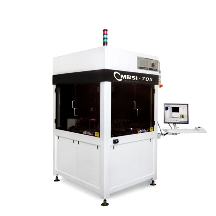
The MRSI-705 is a configurable high-precision die bonder designed around a solid granite overhead platform. Supporting the placement head from above avoids cantilevered mechanisms and improves thermal stability, mechanical stability and settling performance.
Its X and Y axes use actively cooled ironless linear motors with high-resolution linear encoders, while the Z axis uses air-bearing technology. This architecture supports repeatable component placement, high-speed positioning and controlled handling of fragile semiconductor devices.
The platform can be configured for development, prototype, mixed-product or production environments. Typical processes include epoxy die attach, eutectic bonding, flip-chip placement, thermo-compression, in-situ UV curing and integrated dispensing.
This page focuses exclusively on the MRSI-705 model, technical specifications and available configurations. For a broader brand and model introduction, visit our MRSI die bonder system overview.
The specifications below are based on the referenced MRSI-705 technical document. Individual machines may differ according to production year, software, tool banks, bond heads, material handlers and process options.
| Specification | Published Value | Evaluation Note |
|---|---|---|
| Platform structure | Solid granite overhead platform with no cantilevered mechanisms | Designed to improve mechanical and thermal stability. |
| Placement accuracy | ±5 μm at 3 sigma | Actual performance should be confirmed by calibration and acceptance testing. |
| Placement repeatability | ±1.5 μm at 3 sigma | Results depend on tooling, component geometry and machine condition. |
| Placement rate | Up to 1,000 UPH | Reference rate; actual output depends on process steps, vision, travel and material input. |
| Configurable work area | Approximately 700 sq. in. | Usable area changes according to installed feeders, wafer handlers, stages and fixtures. |
| X/Y drive construction | Ironless, zero-force, actively cooled linear motors | Closed-loop positioning through high-resolution linear encoders. |
| X/Y encoder resolution | 0.1 μm | Encoder resolution should not be interpreted as placement accuracy. |
| X/Y speed | 1 m/s or approximately 40 in/s | Maximum axis speed does not represent complete process cycle time. |
| Z-axis placement mode | Place to force or place to height | Applicable mode depends on recipe and installed head configuration. |
| Force control | Programmable per placement with real-time closed-loop feedback | Supports separate force values for different component types. |
| Placement force range | 10 g to 2,000 g | Confirm load cell, bond head and calibration for the required range. |
| Axis | Published Travel | Published Resolution |
|---|---|---|
| X axis | 20.00 in / 508 mm | 0.1 μm |
| Y axis | 25.00 in / approximately 635 mm | 0.1 μm |
| Z axis | 1.25 in / approximately 32 mm | 0.4 μm |
| Theta axis | 360° rotation | 0.004° |
| Specification | Published Configuration | Function |
|---|---|---|
| Vision recognition | Boundary detection and pattern recognition | Locates die centers, edges, application features and substrate fiducials. |
| Die orientation | Full 360° detection and orientation | Supports orientation-critical MMIC, laser and beam-lead components. |
| Downward cameras | Two downward-looking cameras with high and low magnification | Used for component and substrate inspection and alignment. |
| Upward camera | One upward-looking camera | Supports underside inspection and alignment where configured. |
| Lighting | Programmable red, green and blue ring or coaxial lighting | Improves contrast for difficult surfaces such as gold features on alumina. |
| Remote process view | Real-time network camera | Allows remote observation of the operating process. |
| User interface | Windows-based graphical interface | Supports setup, production programming and process operation. |
| Programming data | XML database, CAD download and offline programming support | Facilitates program management and production data integration. |
| Motion control | Up to 32 controlled motion axes | A common controller may manage machine axes and conveyors. |
| Traceability | Barcode program selection, material traceability and network connectivity | Configuration and software version must be verified on the actual machine. |
| Specification | Published Configuration | Capability |
|---|---|---|
| Dual epoxy dispensing | Two-cartridge rotary positive-displacement pumps or time/pressure pumps | Supports die attach, dam-and-fill and lid-attach material dispensing. |
| Height sensor | Three-point laser height measurement | Measures surface tilt before dispensing. |
| Dispense control | Closed-loop servo motor control | Improves material-volume and bond-line control. |
| Needle management | Automatic cleaning, alignment, calibration and priming | Reduces setup effort and improves repeatability between patterns. |
| Dispensing patterns | Small dots, lines and area filling | Suitable configuration depends on pump, needle and material rheology. |
| Minimum epoxy dot | Approximately 0.004 in / 100 μm | Referenced for the appropriate dispensing or stamping configuration. |
| Specification | Published Configuration | Configuration Note |
|---|---|---|
| Pickup tools | Vacuum surface pickup tools | Tool geometry must match die dimensions, surface and fragility. |
| Collet types | Perimeter, two-sided and four-sided inverted-pyramid collets | Custom collet designs may also be used. |
| Standard tool bank | 13-position automatic tool-change bank | Additional tool banks may be installed to hold more tools. |
| Epoxy stamping tools | Stored in the standard 13-position tool bank | Pickup and stamping tools are automatically interchangeable. |
| Optional bond heads | Up to six placement heads | Each configured head may have independent force control. |
| Optional high-volume turret | Up to 12 tools with on-the-fly, zero-time tool change | This is a separate optional configuration, not the standard 13-position tool bank. |
| Specification | Published Capacity | Configuration Note |
|---|---|---|
| Waffle packs and Gel-Paks | Sliding shuttle presentation | Available layout depends on the installed Sector Plate Shuttle. |
| Waffle-pack capacity | Up to 90 × 2 in × 2 in packs | Alternatively, up to 24 × 4 in × 4 in packs or a combined layout. |
| Tape feeders | 8 mm, 16 mm or 24 mm | Multiple feeder bases may be configured. |
| 8 mm feeder capacity | Up to 30 feeders | Exact capacity depends on work-area configuration. |
| Wafer input | Up to 8-inch wafer support | Uses motorized ejector hardware and theta compensation for frame or ring. |
| Wafer functions | Wafer mapping and ink-dot recognition | Helps select known-good die from the wafer. |
| Thin-die handling | Servo-synchronized pickup head and ejector movement | A needleless ejector option may be available for ultra-thin devices. |
| Minimum die size | Documented as approximately 0.006 in square | Confirm tool, vision, ejector and process suitability for very small die. |
| Maximum die size | No practical fixed limit stated | Actual limit depends on work area, mass, tooling, coplanarity and handling. |
| Minimum die thickness | Approximately 0.001 in | Thin-die capability depends on ejector, tool design and die structure. |
| Typical materials | GaAs, InP, silicon and solder preforms | Additional materials may be processed after application evaluation. |
| Product transport | Conveyor for boats, trays, carriers, fixtures, lead frames or boards | Available in standalone, cassette-to-cassette or in-line configurations. |
| Communication | SMEMA-compatible interface | Supports integration with ovens and other production equipment. |
The base platform combines mechanical stability, programmable force, advanced vision and flexible material presentation before application-specific options are added.
The placement head is supported from above without cantilevered mechanisms, helping maintain mechanical and thermal stability during precision production.
Actively cooled ironless linear motors and 0.1 μm encoder resolution support fast motion, controlled settling and repeatable axis positioning.
Placement force can be programmed by component type with real-time feedback for delicate III-V semiconductors, MEMS and thin devices.
Boundary detection, pattern recognition, fiducial alignment and 360-degree orientation support complex optical, RF and multi-chip assemblies.
Ring and coaxial red, green and blue lighting can be adjusted for low-contrast components and challenging reflective surfaces.
Wafer, Gel-Pak, waffle pack, tape feeder and conveyor inputs can be combined according to the required product and production flow.
The MRSI-705 is an open platform. These functions are not automatically included on every machine and must be verified before quotation.
Supports configured epoxy stamping or dispensing before die placement. Multiple epoxy materials and die sizes can be handled on the same platform.
Available configurations may support AuSi, AuSn and AuGe bonding on submounts, TO headers and butterfly packages.
Conveyor-based material handling can combine preheating, pulse-heated bonding, programmable scrub, cover gas and controlled cooling.
Configured flip-chip processes use die orientation, vision alignment and controlled placement for bumped, soldered or adhesive assemblies.
Components can be held in position while UV adhesive is cured, reducing movement after precision placement in optical and AOC assemblies.
Positive-displacement or time-pressure pumps support dots, lines, dam-and-fill material, die attach adhesive and lid attach processes.
A rotary stamping well and interchangeable stamping tools can create epoxy dots down to approximately 100 μm.
Application-specific configurations can support controlled pressure, height and coplanarity for large or high-aspect-ratio devices.
The machine can be configured according to the required production volume, product flow and material presentation method.
Standalone tooling provides greater flexibility for development, prototyping, engineering changes and small-lot production.
Magazine or cassette-based loading reduces manual handling and supports repeated processing of carriers, trays or package fixtures.
SMEMA-compatible material transport can integrate the MRSI-705 with upstream and downstream equipment.
Wafer feeding reduces manual die handling and supports automated selection from mapped or ink-marked wafers.
These are two different MRSI-705 configurations and should not be combined into one specification.
The standard automatic tool-change bank holds pickup collets and epoxy stamping tools. Additional tool banks can be added when a process requires more component-specific tools.
The optional patented turret carries up to 12 tools on the placement head and performs zero-time tool changes to increase output for multi-die and mixed-process products.
The platform is used where placement accuracy, configurable processes, material flexibility and controlled component handling are important.
Multi-die, stacked-device and wafer-level advanced packaging applications.
Laser diodes, lenses, optical modules, transceivers and active optical cables.
MMICs, RF power amplifiers, beam-lead devices and hybrid microwave assemblies.
Pressure sensors, infrared sensors and devices containing fragile microstructures.
Precision assembly of LED devices and related optoelectronic packages.
Complex products containing several die types, dimensions and bonding processes.
Medical imaging, hearing devices, pacemaker components and other precision assemblies.
High-reliability hybrid circuits and mission-critical semiconductor packages.
The MRSI-705 model name alone does not identify all installed capabilities. Provide the application information below so that the available machine can be evaluated against your process.
Our work is focused on matching the available equipment configuration to the intended process rather than offering an unidentified machine by model name alone.
Confirm the model plate, serial number, production year, software and installed hardware.
Check bond heads, tool banks, vision, wafer handling, feeders, stages and process modules.
Review current photographs, power-on status, calibration information and known faults.
Support packing, shipping, installation planning, parts preparation and technical follow-up.
Each page serves a separate search and procurement requirement, reducing content overlap between the MRSI brand page and individual model pages.
Send your process and component information so that the available MRSI-705 configuration can be checked against the required bonding, handling and production conditions.
Please provide as much application information as possible for a more accurate equipment evaluation.