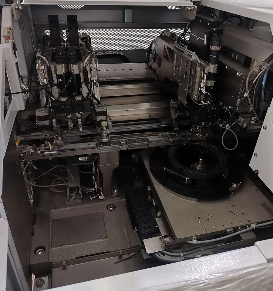
The ASM AD830 Plus is an automatic die bonding platform that combines wafer handling, die recognition, ejector-assisted die separation, vacuum pickup, silver-epoxy application, lead-frame transport, programmed die placement and optical inspection.
When an AD830 Plus stops repeatedly, reports a missing-die condition, fails pattern recognition or produces unstable epoxy deposits, replacing the first suspected component is rarely the best diagnostic method. The alarm usually identifies the stage where the process stopped, but the root cause may be located in the tooling, material, vacuum circuit, mechanical position, vision reference or package settings.
This practical guide explains how to investigate common ASM AD830 Plus troubleshooting problems, including:
Missing-die alarms
Unstable die pickup
Die cracking or chipping
Wafer PR and lead-frame PR failures
Inconsistent epoxy dispensing or stamping
Die-placement offset and rotation
Lead-frame transfer jams
Bond-head and motion alarms
Preventive maintenance planning
AD830 spare-parts preparation
Safety notice: This guide is intended for process review and preliminary fault isolation. Electrical cabinets, servo systems, safety circuits, pneumatic components and moving mechanisms should only be inspected by qualified personnel. Follow the machine manual and factory lockout procedures. Never bypass a safety door, interlock, emergency-stop circuit or protective cover to continue production.
Quick ASM AD830 Plus Troubleshooting Table
Use the following table to identify the most likely inspection area before changing machine parameters or replacing parts.
| Machine Symptom | Likely System | First Items to Check | Possible Parts or Tools |
|---|---|---|---|
| Missing-die alarm | Vacuum pickup or die release | Collet cleanliness, vacuum reading, pickup height, ejector action and wafer tape | Collet, vacuum tube, pneumatic fitting, sensor, ejector pin |
| Die remains on wafer tape | Ejector and wafer support | Ejector-pin height, tip condition, wafer expansion, tape adhesion and pickup timing | Ejector pin, ejector cap, wafer-expansion components |
| Die falls after pickup | Vacuum circuit or collet | Vacuum leakage, collet opening, vacuum delay, tubing and die-to-collet fit | Collet, hose, connector, valve or vacuum sensor |
| Die cracks during pickup | Ejector, collet or force setting | Ejector geometry, pin position, pickup height, collet contact and wafer-tape condition | Ejector pin, ejector cap and collet |
| Wafer PR failure | Vision system or wafer condition | Focus, lighting, lens cleanliness, reference image, search area and wafer position | Camera, lens, light source, cable or vision controller |
| Lead-frame PR failure | Vision, material position or clamping | Frame location, clamp condition, contrast, lighting and reference feature | Camera, lighting unit, clamp, anvil or position sensor |
| Missing or unstable epoxy | Dispensing or stamping system | Epoxy condition, pressure, needle or stamp, process height, delay and contamination | Needle, syringe, stamp tool, tray, seal, motor or sensor |
| Die-placement offset | PR, tooling or mechanical reference | Vision repeatability, theta correction, collet wear, bond height and lead-frame support | Collet, camera, encoder, anvil, clamp or bond-head component |
| Lead-frame transfer jam | Input, track, work holder or output | Track width, frame flatness, magazine alignment, pusher and sensors | Sensor, pusher, belt, guide, motor or magazine component |
| Repeated bond-head alarm | Motion, cable, motor or mechanical system | Obstruction, tool collision, cable condition, encoder feedback and abnormal resistance | Motor, encoder, driver, cable, bearing or mechanical linkage |
Before Troubleshooting an AD830 Plus
Do not begin by changing multiple parameters. If several settings are adjusted at the same time, it becomes difficult to identify which change corrected or worsened the fault.
Before opening a machine cover or editing the package file, complete the following checks:
Record the full alarm message and alarm time.
Take a screenshot of the machine interface.
Record which process station stopped.
Identify whether the fault affects every product or only one package.
Confirm whether the problem began after maintenance, tool replacement or material change.
Save or back up the current package parameters before making changes.
Check whether the same alarm occurs at the same physical position.
Use a short video to record the process immediately before the alarm.
Inspect for contamination, loose tools and obvious mechanical interference.
Change only one controlled variable at a time.
Machine Problem or Process Problem?
A useful first step is to determine whether the problem follows the machine, package, material or tool.
| Diagnostic Test | Possible Conclusion |
|---|---|
| The same package runs normally on another AD830 Plus | The problem is more likely related to machine configuration, calibration, tooling or hardware. |
| Multiple packages show the same fault on one machine | Investigate a shared machine system such as vacuum, vision, motion or material transport. |
| Only one wafer or material batch shows the problem | Review wafer tape, die condition, lead-frame dimensions, epoxy or material handling. |
| The fault started immediately after tool replacement | Check tool dimensions, installation height, alignment and calibration. |
| The fault started after package-file editing | Compare the current package with the last known stable backup. |
| The fault occurs only after extended production | Investigate contamination, temperature, epoxy working time, vacuum degradation or mechanical heating. |
1. ASM AD830 Plus Missing-Die Alarm
A missing-die alarm generally means that the machine did not detect the expected die after the pickup sequence. It does not automatically mean the missing-die sensor is defective.
The die may have:
Remained on the wafer tape
Failed to seal against the collet
Been picked and then dropped
Moved inside the collet
Been damaged during ejection
Been present but not detected because of unstable vacuum
Check the Collet First
Remove the collet according to the approved maintenance procedure and inspect:
The die-contact surface
The vacuum opening
Epoxy contamination
Particles or broken-die fragments
Wear around the die pocket
Cracks or deformation
Correct mounting and orientation
A partially blocked vacuum opening may still create a vacuum reading without providing enough airflow or holding force for reliable pickup. A worn pocket can also allow the die to rotate or lose its seal during movement.
Inspect the Vacuum Circuit
Check the complete vacuum path rather than only the sensor:
Verify the vacuum source.
Inspect flexible tubing for cracks, pinching and contamination.
Check pneumatic connectors and fittings.
Confirm that valves switch consistently.
Compare vacuum readings with and without a die.
Observe whether the reading changes during bond-head movement.
Check detection thresholds only after the physical vacuum system is stable.
If the vacuum value changes when the bond arm moves, inspect tubing routing, cable-chain movement and loose connections.
Check Pickup Height and Timing
An incorrect pickup height can produce several different symptoms:
The collet does not contact the die sufficiently.
The collet presses too heavily against the die.
The die lifts and then falls back onto the wafer tape.
The ejector and bond head operate out of synchronization.
The die becomes tilted inside the collet.
Confirm the mechanical reference, collet length, die thickness and pickup position before adjusting the package setting.
Check the Ejector System
The ejector should support die release without cracking, tilting or shifting the die. Inspect:
Ejector-pin tip condition
Ejector-pin straightness
Pin height and travel
Pin location under the die
Ejector-cap opening and support
Wafer-tape tension
Wafer expansion
Timing between ejection and pickup
A missing-die alarm that appears mainly at the wafer edge may indicate a wafer-expansion, frame-flatness or ejector-position issue rather than a vacuum-sensor failure.
Need Help Diagnosing an AD830 Missing-Die Alarm?
Send the alarm screenshot, collet photograph, ejector video, vacuum reading, die dimensions and wafer-tape information. These details make it easier to separate a tooling problem from a vacuum, ejector or parameter issue.
2. Unstable Die Pickup or Die Dropping
An AD830 Plus may successfully pick a die but lose it during rotation, transfer or movement toward the bonding position. This problem often differs from a complete pickup failure.
Typical Symptoms
The die is visible inside the collet immediately after pickup but disappears before bonding.
The machine passes the initial pickup check but reports a missing die later.
The die rotates inside the collet.
The die is placed at an inconsistent angle.
Dropped dies are found inside the machine.
The problem becomes worse at higher production speed.
Possible Causes
The collet pocket is too large for the die.
The vacuum opening is not positioned correctly.
The die surface does not form a stable seal.
The vacuum tube leaks during arm movement.
The die is tilted during ejection.
The pickup height is incorrect.
Bond-arm acceleration is too aggressive for the process condition.
Contamination reduces the die-to-collet contact area.
Recommended Diagnostic Order
Clean and inspect the collet.
Confirm the collet dimensions against the die drawing.
Check vacuum stability during the complete movement cycle.
Observe die orientation immediately after pickup.
Inspect the ejector-pin position and action.
Check pickup height and die thickness.
Run repeated pickup tests at reduced speed.
Increase speed only after pickup becomes stable.
Do not compensate for a damaged or incorrect collet by continually increasing pickup force or vacuum thresholds. This may hide the original problem and increase die damage.
3. Die Cracking, Chipping or Surface Damage
Die cracking can occur during ejection, pickup, transfer or bonding. The location and shape of the damage can help identify the responsible stage.
| Damage Observation | Possible Area | Checks |
|---|---|---|
| Crack near the center of the die | Ejector-pin force or unsupported die area | Pin height, tip geometry, ejector cap and wafer-tape support |
| Chipped die edge | Collet pocket or lateral die movement | Collet size, pocket wear, die rotation and pickup alignment |
| Scratches on the die surface | Contaminated or damaged collet | Contact surface, embedded particles and cleaning method |
| Damage appears after bonding | Bond height, force or substrate support | Bond level, force setting, anvil, clamp and substrate flatness |
| Damage occurs mainly on thin dies | Tooling and process window | Pin design, pickup force, tape condition and support geometry |
Do Not Ignore Wafer-Tape Condition
The same machine setting may behave differently when the wafer tape changes. Review:
Tape type
Adhesion level
UV treatment condition where applicable
Wafer-mounting quality
Expansion amount
Storage time
Temperature and environmental condition
Before changing mechanical calibration, compare a problematic wafer with a known stable wafer whenever possible.
4. Wafer PR Failure
A clear camera image does not prove that pattern recognition is stable. The AD830 Plus must repeatedly identify the correct reference at the required speed and under normal production variation.
Initial Vision Checks
Clean the camera window and lens area.
Confirm that the image is in focus.
Check lighting intensity and uniformity.
Verify the correct package file.
Confirm the correct wafer and die reference.
Check whether the search area contains unnecessary features.
Inspect the wafer for contamination, reflections or damaged dies.
Confirm that wafer theta and coordinate references are correct.
Reference Image Problems
A reference image may work during initial setup but become unstable during production if:
The selected feature is not unique.
The search area includes neighboring dies or street patterns.
The lighting changes across the wafer.
The die surface is highly reflective.
The wafer contains different process variations.
The reference was created from an abnormal die.
Choose a stable and repeatable feature instead of simply increasing the PR tolerance.
Intermittent PR Failure
When the failure is intermittent, investigate:
Loose camera or lighting cables
Lighting-source instability
Mechanical vibration
Focus movement
Wafer-table repeatability
Temperature-related behavior
Communication or controller errors
Record whether the fault appears at one wafer position, after a certain running time or during a specific bond-head movement.
5. Lead-Frame PR Failure
Lead-frame recognition problems are not always caused by the camera. The frame may be physically positioned incorrectly, unsupported or moving during image acquisition.
Check Material Position First
Is the lead frame fully indexed into position?
Is the frame flat against the support?
Does the window clamp hold the material consistently?
Is the magnetic anvil installed correctly?
Is the lead frame warped or contaminated?
Does the track width match the material?
Is there epoxy contamination around the support area?
Check Image Contrast
Lead-frame surfaces can create strong reflections. Review:
Lighting direction
Lighting intensity
Exposure setting
Reference-feature selection
Background and frame contrast
Surface finish and plating variation
Avoid using an edge or feature that changes between material suppliers or production batches.
6. Epoxy Dispensing and Stamping Problems
Silver-epoxy behavior changes with material condition, temperature, pressure, time, tooling and process height. A stable mechanical movement cannot compensate for unsuitable or expired process material.
Common Epoxy Symptoms
Missing epoxy deposit
Deposit too small
Deposit too large
Unstable deposit volume
Epoxy tailing or stringing
Bridging between bonding positions
Deposit-position offset
Epoxy contamination on tools or lead-frame surfaces
Air bubbles inside the deposit
Material curing or thickening during production
Epoxy Material Checks
Confirm:
Correct epoxy type
Material batch
Storage condition
Thawing procedure
Mixing procedure where required
Working time after preparation
Ambient temperature
Material contamination
Dispensing-System Checks
Syringe installation
Needle type and internal diameter
Needle blockage or damage
Air pressure and pressure stability
Dispensing delay
Needle height
Deposit time
Valve, motor and actuator response
Hose and connector condition
Stamping-System Checks
Stamp-tool shape and wear
Stamping depth
Epoxy-tray level
Epoxy distribution inside the tray
Tool cleanliness
Transfer height
Stamping-arm repeatability
Material drying around the tool
Recommended Epoxy Diagnostic Method
Stop die placement and inspect epoxy deposits alone.
Produce a repeated deposit pattern on representative lead frames.
Measure position, size and consistency.
Confirm material working time and temperature.
Clean or replace the dispensing or stamping tool.
Change only one pressure, height or timing variable at a time.
Reintroduce die placement after the deposit becomes stable.
Need AD830 Epoxy-System Parts?
Send the epoxy-station photograph, needle or stamping-tool dimensions, machine serial number and a short video of the unstable deposit. This helps identify the required tool, sensor, actuator or material-handling component.
7. Die-Placement Offset or Rotation
Placement offset may come from the vision system, wafer correction, die movement inside the collet, bond-head mechanics or lead-frame support.
Identify Whether the Offset Is Consistent
A consistent offset and a random offset usually have different causes.
| Offset Pattern | Possible Cause |
|---|---|
| Same X-Y offset on every die | Recipe offset, reference teaching or mechanical calibration |
| Random X-Y variation | PR instability, die movement in collet, material movement or mechanical repeatability |
| Rotation varies randomly | Collet fit, vacuum stability, theta correction or die release |
| Offset changes by lead-frame position | Material support, track reference, frame warpage or local PR reference |
| Offset increases after long production | Tool contamination, mechanical heating, material variation or focus change |
Recommended Check Order
Verify PR search repeatability without bonding.
Confirm wafer theta and die orientation.
Inspect whether the die moves inside the collet.
Check the collet for wear and contamination.
Confirm pickup and bond heights.
Check lead-frame clamping and anvil support.
Inspect bond-head movement for abnormal play or resistance.
Review encoder and calibration results.
Compare the current package with a stable backup.
Do not correct random mechanical variation by adding a fixed recipe offset. A fixed offset may improve one sample while increasing variation elsewhere.
8. Lead-Frame Transfer Jam
Lead-frame transport involves the input magazine or stack loader, pusher, track, work-holder area, clamp, anvil, sensors and output elevator. A jam can originate before or after the physical location where the frame stops.
Input-Side Checks
Correct magazine dimensions
Correct slot pitch
Magazine alignment
Lead-frame orientation
Pusher alignment
Frame separation
Input sensor condition
Magazine-elevator movement
Track and Work-Holder Checks
Track width
Guide cleanliness
Lead-frame flatness
Magnetic-anvil position
Window-clamp clearance
Epoxy contamination
Loose screws or displaced guides
Sensor alignment
Output-Side Checks
Output magazine position
Magazine slot alignment
Elevator movement
Finished-frame flatness
Pusher stroke
Output sensor response
Material Variation
If the machine runs one lead-frame batch but jams with another, compare:
Overall width
Thickness
Flatness
Burrs
Surface contamination
Strip curvature
Supplier tolerance
Do not increase transport force before confirming that the material can move freely through the complete path.
9. Bond-Head and Motion Alarms
A repeated bond-head alarm can be caused by mechanical interference, excessive resistance, a damaged tool, cable problems, encoder feedback, motor condition or driver faults.
Stop the Machine Immediately When:
A tool collision has occurred.
The bond head makes an abnormal mechanical noise.
The axis cannot home normally.
The machine reports repeated position errors.
A motor, driver or cable becomes unusually hot.
There is visible cable or connector damage.
The axis moves unexpectedly.
The safety circuit does not function correctly.
Preliminary Inspection
Record the alarm and axis position.
Check for physical obstruction.
Inspect whether the tool or collet is installed incorrectly.
Check cables and connectors visible in the approved service area.
Review whether the alarm started after maintenance or a collision.
Do not repeatedly reset and restart an axis with abnormal resistance.
Arrange qualified electrical or motion-system inspection when required.
Replacing a motor or driver without checking mechanical resistance, cables and feedback can result in repeated component failure.
10. Preventive Maintenance Schedule for ASM AD830 Plus
The actual maintenance frequency should be adjusted according to production volume, epoxy contamination, wafer condition, tool wear, factory procedures and the approved machine manual.
| Suggested Frequency | Maintenance Area | Recommended Work |
|---|---|---|
| Every Shift | Production and tooling | Check alarms, inspect the collet, remove visible epoxy contamination and verify vacuum pickup. |
| Daily | Wafer, track and vision | Clean approved wafer-table surfaces, transport guides, camera windows and accessible work-holder areas. |
| Daily | Epoxy process | Inspect needles or stamping tools, trays, syringes, pressure and material condition. |
| Weekly | Pickup system | Inspect collets, ejector pins, ejector caps, vacuum tubing, fittings and pickup repeatability. |
| Weekly | Material handling | Inspect magazines, pushers, sensors, track guides, clamps, anvils and output transfer. |
| Monthly | Motion and cables | Inspect visible cable routing, connectors, abnormal noise, axis repeatability and signs of collision. |
| Monthly | Vision system | Check focus, lighting consistency, PR repeatability and camera-image stability. |
| Quarterly or by usage | Process verification | Complete repeated pickup, placement, inspection and material-transfer checks using representative samples. |
| After Collision | Mechanical and calibration | Inspect tools, bond head, ejector, work holder, cameras and calibration before restarting production. |
| Before Long Shutdown | Data and preservation | Back up package files, record settings, remove process material and protect sensitive areas. |
Recommended AD830 Plus Spare Parts
A practical spare-parts plan should focus on wear parts, contamination-sensitive parts and components that can stop production.
Pickup and Ejector Parts
Product-specific collets
Ejector pins
Ejector caps
Vacuum tubing
Pneumatic fittings
Vacuum filters
Vacuum sensors or switches
Epoxy-System Parts
Dispensing needles
Syringes and holders
Stamping tools
Epoxy trays
Seals and connectors
Pressure-related components
Epoxy-level or position sensors
Material-Handling Parts
Position sensors
Pusher components
Belts where applicable
Magazine-handling components
Guide and track parts
Clamp components
Magnetic anvils
Vision-System Parts
Cameras
Lenses
Lighting units
Camera cables
Lighting cables and controllers
Motion and Electrical Parts
Motors
Encoders
Motor drivers
Control boards
Power supplies
I/O modules
Machine cables
Confirm every part using the machine serial number, installed-module photograph, old-part label and connector details. Do not purchase an AD830 component from the machine model alone.
Information Required for Remote AD830 Troubleshooting
A message saying “the AD830 does not work” is not enough to identify the failed system. Prepare the following diagnostic package:
Exact machine model
Machine serial number
Manufacturing year
Software version where available
Full alarm text and code
Alarm screenshot
Video showing the sequence before the alarm
Photograph of the affected station
Information about recent maintenance or collisions
Recently replaced parts
Die dimensions and thickness
Wafer size and wafer-tape information
Lead-frame dimensions
Epoxy type and process
Collet and ejector photographs
Vacuum reading where relevant
Frequency of the fault
Whether the fault affects one package or all packages
Request ASM AD830 Plus Technical Support
We support customers reviewing ASM AD830 Plus machine faults, replacement parts, tooling requirements, used-machine configurations and production compatibility.
Send the machine serial number, alarm screenshot, affected-module photograph and a short operating video. For pickup or placement problems, also include the die, wafer, lead-frame, collet and ejector information.
When Should the Machine Be Checked by an Engineer?
Stop preliminary operation and arrange qualified technical inspection when:
The machine has experienced a bond-head or tooling collision.
An axis cannot home or moves abnormally.
Electrical burning, unusual heat or smoke is detected.
A safety interlock or emergency circuit is unreliable.
The same motor or driver fails repeatedly.
The machine shows significant mechanical vibration.
Calibration cannot be completed.
Placement variation remains after tooling and process checks.
A control board, servo system or high-voltage circuit requires testing.
The repair requires machine alignment or precision measurement equipment.
Related ASM AD830 Plus Resources
For equipment configuration, process compatibility and package transfer, read theASM AD830 die bonder process and setup guide.
For available equipment, inspection scope, machine condition and quotation requirements, review theused ASM AD830 Plus die bonder.
For more semiconductor die attach equipment, visit thedie bonder equipment section.
Frequently Asked Questions
Why does an ASM AD830 Plus report a missing-die alarm?
The die may remain on the wafer tape, fail to seal against the collet, drop during movement or produce an unstable vacuum reading. Check the collet, vacuum circuit, pickup height, ejector action, wafer expansion and tape condition before replacing the missing-die sensor.
Why does the die remain on the wafer tape?
Possible causes include insufficient ejector height, a worn or incorrect ejector pin, high tape adhesion, unstable wafer expansion, incorrect pickup timing, an unsuitable collet or an incorrect pickup height.
What causes unstable die pickup?
Common causes include a blocked or worn collet, vacuum leakage, incorrect die-to-collet fit, unsuitable pickup height, unstable die release, damaged tubing or excessive die movement during bond-arm acceleration.
Why does the AD830 Plus fail wafer pattern recognition?
Check camera focus, lens cleanliness, lighting, reference-image quality, search area, wafer position, wafer theta and the selected package file. A clear camera image does not necessarily provide stable pattern recognition.
What causes unstable silver-epoxy deposits?
Epoxy condition, working time, viscosity, temperature, air pressure, needle or stamp condition, process height, timing, tray level and contamination can all affect deposit size and repeatability.
Why is the die placed with an offset or incorrect rotation?
Possible causes include unstable PR, incorrect reference teaching, die movement inside the collet, collet wear, wafer-theta error, unsuitable bond height, lead-frame movement, poor anvil support or mechanical calibration problems.
Why does the lead frame jam inside the AD830 Plus?
Inspect magazine alignment, track width, lead-frame flatness, pusher movement, guides, clamps, anvils, sensors and output-magazine position. Epoxy contamination or material burrs can also restrict transport.
How often should the AD830 collet be cleaned?
Cleaning frequency depends on production volume, die condition, epoxy contamination and factory procedures. The collet should be inspected regularly and cleaned whenever contamination, unstable pickup or die movement is observed.
Which AD830 spare parts should be kept in stock?
Commonly prepared items include collets, ejector pins, ejector caps, vacuum tubing, pneumatic fittings, dispensing needles, stamping tools, sensors and product-specific anvils or clamps. Critical electronic parts should be selected according to machine condition and production risk.
Can an AD830 Plus be diagnosed from an alarm code alone?
An alarm code is useful, but it usually identifies only the stage where the process stopped. Accurate diagnosis also requires the machine serial number, fault video, affected station, material information, maintenance history and relevant parameter or vacuum readings.
Can the machine be tested without wafers and lead frames?
A dry cycle can confirm basic movement, but it cannot fully evaluate die release, vacuum pickup, epoxy behavior, material transfer, placement quality or inspection stability. Representative production material is recommended for final verification.